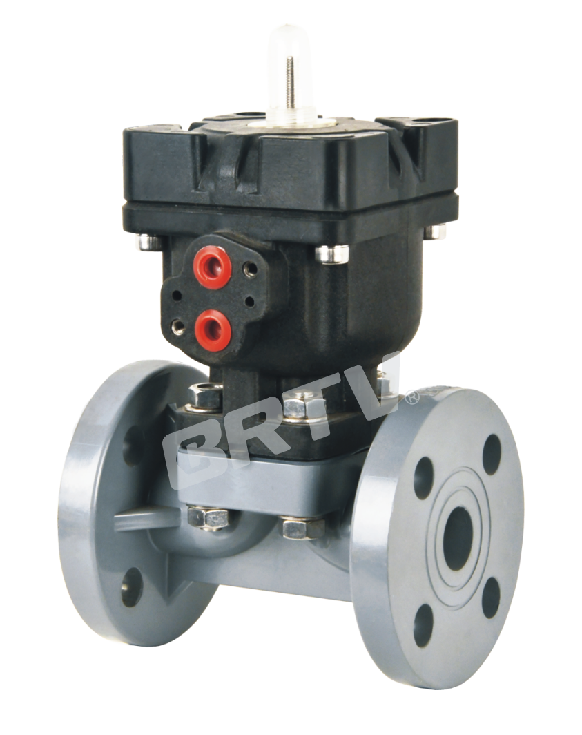
All-Plastic Pneumatic Diaphragm Valve
Features
• Long service life and excellent sealing performance.
• All-plastic design, lightweight, with outstanding corrosion resistance.
• Easily compatible with various pneumatic accessories.
• Large flow capacity with low flow resistance; can be equipped with a positioner for remote and precise flow control.
• Designed with an adjustable closing stroke positioning structure to extend diaphragm life and simplify maintenance.
• Invention patent number: ZL202111674037.9
Optional Parameter List
| Body Material | Diaphragm Material | Connection Type | Connection Standard | Action | Option |
|---|
| FRPP | PTFE | Flange Type | HG | Double Acting PN10 | Limit Switch |
| PPH | PFA | True Union Type | DIN | Air to Close PN10 | Speed Controller |
| CPVC | F46 | — | ANSI | Air to Open PN6 | Solenoid Valve |
| UPVC | EPDM | — | JIS | Air to Open PN10 | Positioner |
| PVDF | FKM | — | — | — | Filter Regulator |
Product advantage
• Diaphragm valves are highly suitable for pneumatic applications, offering reliable cylinder performance and rapid opening and closing.
• Pneumatic plastic diaphragm valves are much lighter than pneumatic metal diaphragm valves or ball valves, making installation and operation easier.
• The consistent valve body structure allows direct replacement of manual diaphragm valves on pipelines with pneumatic diaphragm valves.
• Automatic valves reduce the need for workers to come into contact with hazardous media, improving operational safety.
• It is recommended to install a backup manual valve at the location of the automatic valve to handle unexpected situations such as power failure, gas supply interruption, or control system failure.
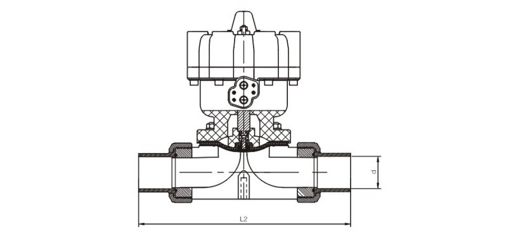
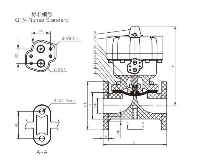
Dimension Table
| DN | D (mm) DIN | D (mm) JIS | D (mm) ANSI | L (mm) DIN | L (mm) JIS | L (mm) ANSI | Socket End d (mm) DIN | JIS | ANSI | Thread End d | JIS | ANSI | L2 (mm) |
|---|
| 15 | 65 | 70 | 60 | 125 | 110 | 110 | 20 | 22 | 21.3 | Rc1/2 | PT1/2 | NPT1/2 | 155 |
| 20 | 75 | 75 | 70 | 135 | 120 | 120 | 25 | 26 | 26.7 | Rc3/4 | PT3/4 | NPT3/4 | 165 |
| 25 | 85 | 90 | 79 | 145/160 | 130 | 130 | 32 | 32 | 33.4 | Rc1 | PT1 | NPT1 | 173 |
| 32 | 100 | 100 | 89 | 160/180 | 160 | 160 | 40 | 38 | 42.2 | Rc1-1/4 | PT1-1/4 | NPT1-1/4 | 248 |
| 40 | 110 | 105 | 98 | 180 | 180 | 180 | 50 | 48 | 48.3 | Rc1-1/2 | PT1-1/2 | NPT1-1/2 | 257 |
| 50 | 125 | 120 | 121 | 210 | 210 | 210 | 65 | 60 | 60.3 | Rc2 | PT2 | NPT2 | 292 |
actuator parameter table
Actuator Specification (Double Acting)
| DN (mm) | 15 | 20 | 25 | 32 | 40 | 50 |
|---|
| Operating Pressure (MPa) | 0.4–0.6 | | | | | |
| Air Consumption (0.4 MPa) | 25 | 1.25 | 1.29 | 1.29 | 4.35 | 4.8 |
| Air Supply Bore | RC 1/4 | | | | | |
Actuator Specification (Air to Open)
| DN (mm) | 15 | 20 | 25 | 32 | 40 | 50 |
|---|
| Operating Pressure (MPa) | 0.4–0.6 | | | | | |
| Air Consumption (0.5 MPa) | 25 | 1.25 | 1.29 | 1.29 | 4.35 | 4.8 |
| Air Supply Bore | RC 1/4 | | | | | |
| DN (mm) | 15 | 20 | 25 | 32 | 40 | 50 |
|---|
| Operating Pressure (MPa) | 0.4–0.6 | | | | | |
| Air Consumption (0.4 MPa) | 25 | 1.25 | 1.29 | 1.29 | 4.35 | 4.8 |
| Air Supply Bore | RC 1/4 | | | | | |
When the gas supply of the double-acting actuator is interrupted, the valve remains in its original position for a certain period of time.
When ventilation is open and the actuator gas supply is interrupted, the valve closes.
When ventilation is closed and the actuator gas supply is interrupted, the valve opens.
Pneumatic Diaphragm Valve with Metal Actuator
Features
• Split structure with metal actuator, allowing easy maintenance and installation.
• Large flow capacity and low flow resistance; can be equipped with a positioner for remote and precise flow control.
• Only single-acting normally closed diaphragm valves with standard closing stroke are provided.
Optional Parameter List
| Body Material | Diaphragm Material | Connection Type | Connection Standard | Action | Option |
|---|
| FRPP | PTFE | Flange Type | HG | Air to Open PN6 | Limit Switch |
| PPH | PFA | True Union Type | DIN | — | Solenoid Valve |
| CPVC | F46 | — | ANSI | — | Filter Regulator |
| UPVC | EPDM | — | JIS | — | — |
| PVDF | FKM | — | — | — | — |
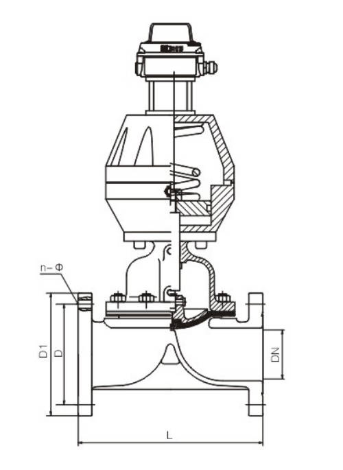
Dimension Table
| DN | D (mm) DIN | D (mm) JIS | D (mm) ANSI | L (mm) DIN | L (mm) JIS | L (mm) ANSI | n (DIN) | n (JIS) | n (ANSI) | Φ (mm) DIN | Φ (mm) JIS | Φ (mm) ANSI |
|---|
| 15 | 65 | 70 | 60 | 125 | 110 | 110 | 4 | 4 | 4 | 14 | 15 | 16 |
| 20 | 75 | 75 | 70 | 135 | 120 | 120 | 4 | 4 | 4 | 14 | 15 | 16 |
| 25 | 85 | 90 | 79 | 145/160 | 130 | 130 | 4 | 4 | 4 | 14 | 15 | 16 |
| 32 | 100 | 100 | 89 | 160/180 | 160 | 160 | 4 | 4 | 4 | 18 | 19 | 16 |
| 40 | 110 | 105 | 98 | 180 | 180 | 180 | 4 | 4 | 4 | 18 | 19 | 16 |
| 50 | 125 | 120 | 121 | 210/230 | 210 | 210 | 4 | 4 | 4 | 18 | 19 | 19 |
| 65 | 145 | 140 | 140 | 250 | 250 | 250 | 4 | 4 | 4 | 18 | 19 | 19 |
| 80 | 160 | 150 | 152 | 300 | 280 | 280 | 8 | 8 | 4* | 18 | 19 | 19 |
| 100 | 180 | 175 | 190 | 350 | 340 | 340 | 8 | 8 | 8 | 18 | 19 | 19 |
| 125 | 210 | 210 | 216 | 400 | 410 | 410 | 8 | 8 | 8 | 18 | 19 | 22 |
| 150 | 240 | 240 | 241 | 460 | 480 | 480 | 8 | 8 | 8 | 22 | 23 | 22 |
Manufacturing Process
Step 1: Order and Design
Based on the customer’s operating conditions (pressure, temperature, and medium), we finalize the design plan, determine the valve body material (e.g., PVC, PP, PVDF) and actuator specifications, and complete the structural design and drawing output for the pneumatic diaphragm valve.
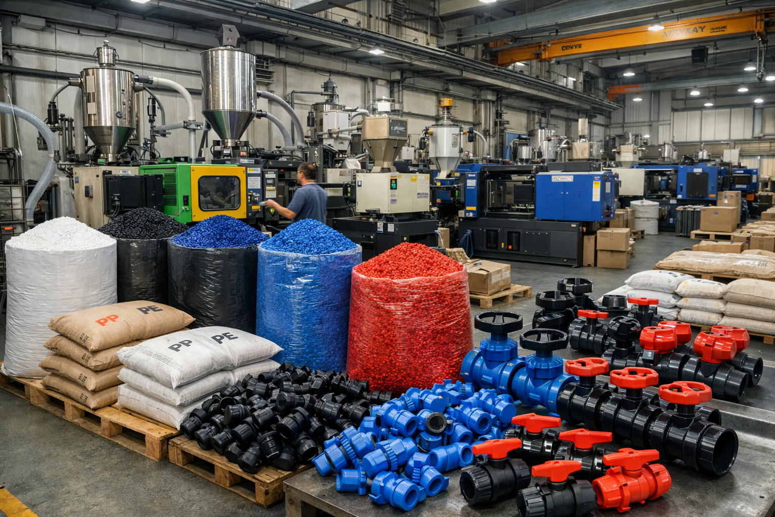
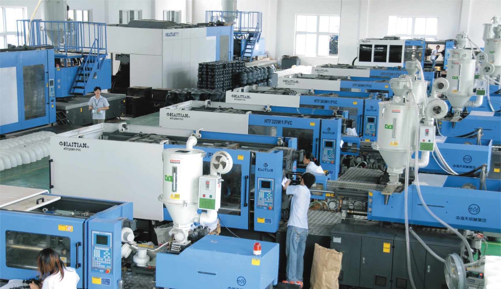
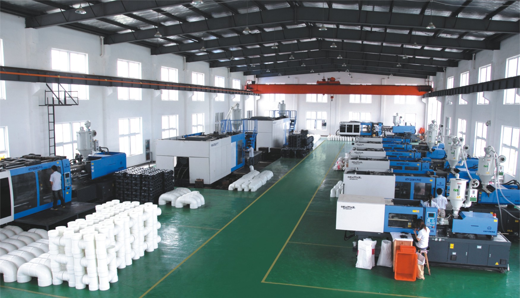
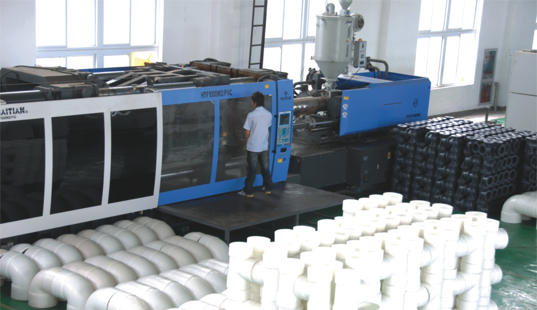
Step 2: Raw Material Preparation & Molding
Select high-quality plastic raw materials and perform drying treatment. Mold the valve body, diaphragm, and key components using injection molding or compression molding processes to ensure the pneumatic diaphragm valve’s corrosion resistance and dimensional stability.
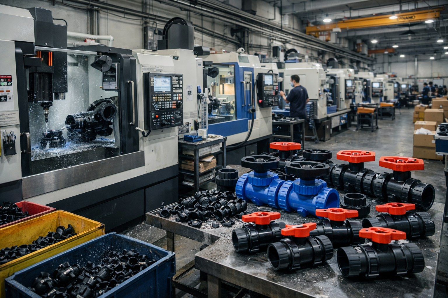
Step 3: Machining
Perform precision machining on the molded valve body, including flange face turning, sealing surface finishing, and threading, to ensure the sealing performance and assembly accuracy of the pneumatic diaphragm valve.
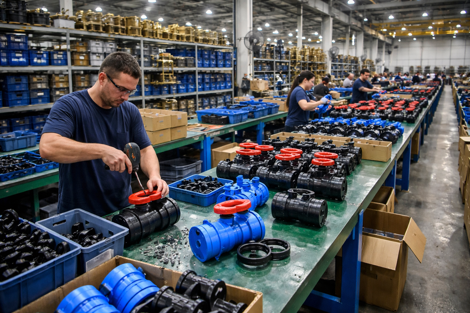
Step 4: Assembly
Assemble the diaphragm, valve body, valve cover, and pneumatic actuator; adjust the stroke and pneumatic control components to ensure the pneumatic diaphragm valve opens and closes smoothly with precise response.
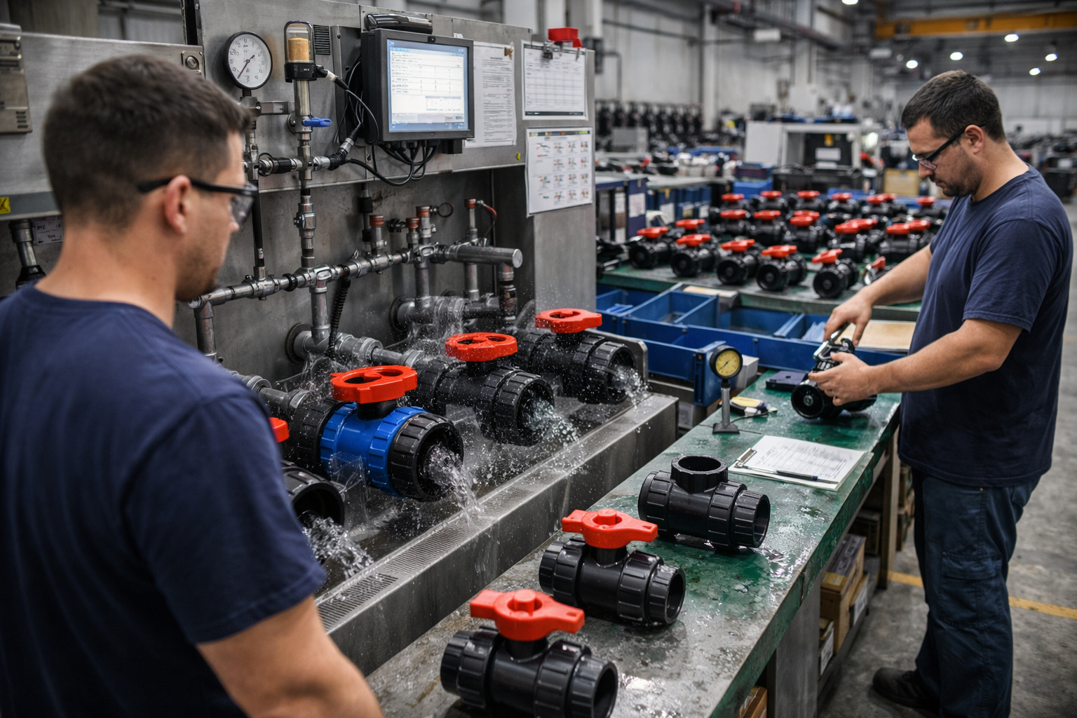
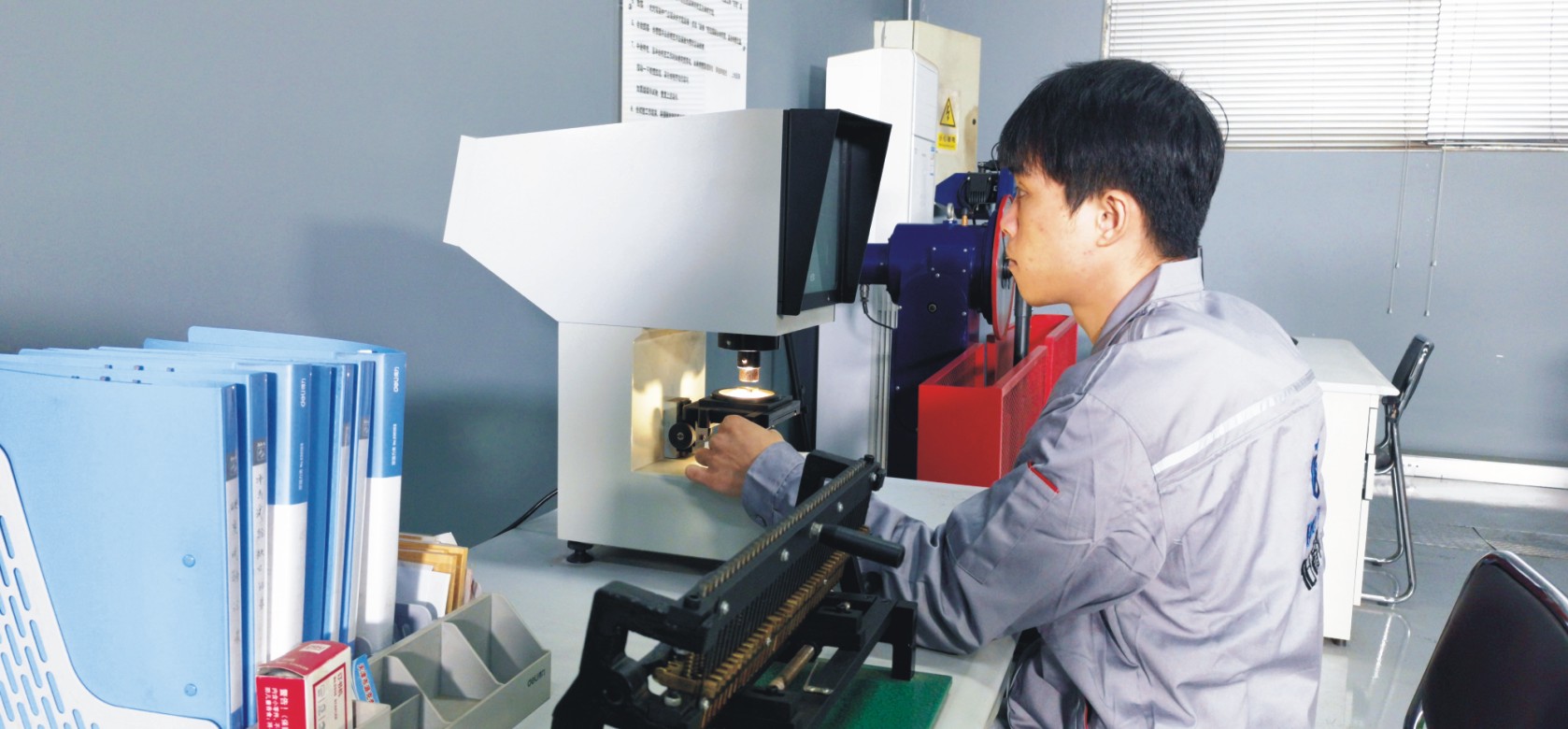
Step 5: Testing & Quality Assurance
The finished product undergoes air tightness, strength, and operational testing (such as pneumatic drive testing) to comprehensively verify that the pneumatic diaphragm valve’s performance meets standard requirements.
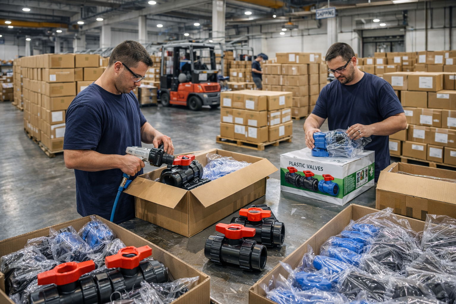
Step 6: Finishing, Packaging and Shipment
The product surface is cleaned, marked, and treated with protective coatings. Appropriate packaging methods are used to prevent damage during transport, and the product is prepared for warehousing and shipment.
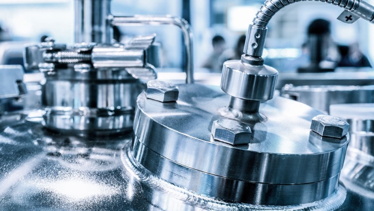
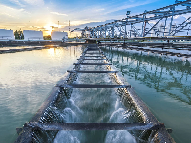
Applications
Widely used in the chemical (strong acids and alkalis/solvents), pharmaceutical and food (aseptic processes), water treatment (wastewater/dosing systems), and power generation industries, these systems are specifically designed to handle corrosive, viscous, abrasive, or high-purity fluids.
These valves are widely used in:
Agriculture and Irrigation
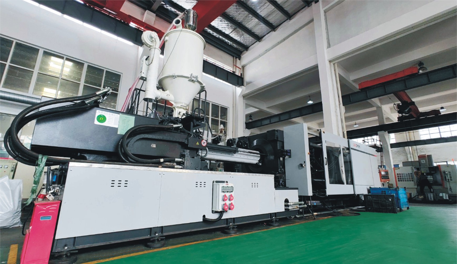
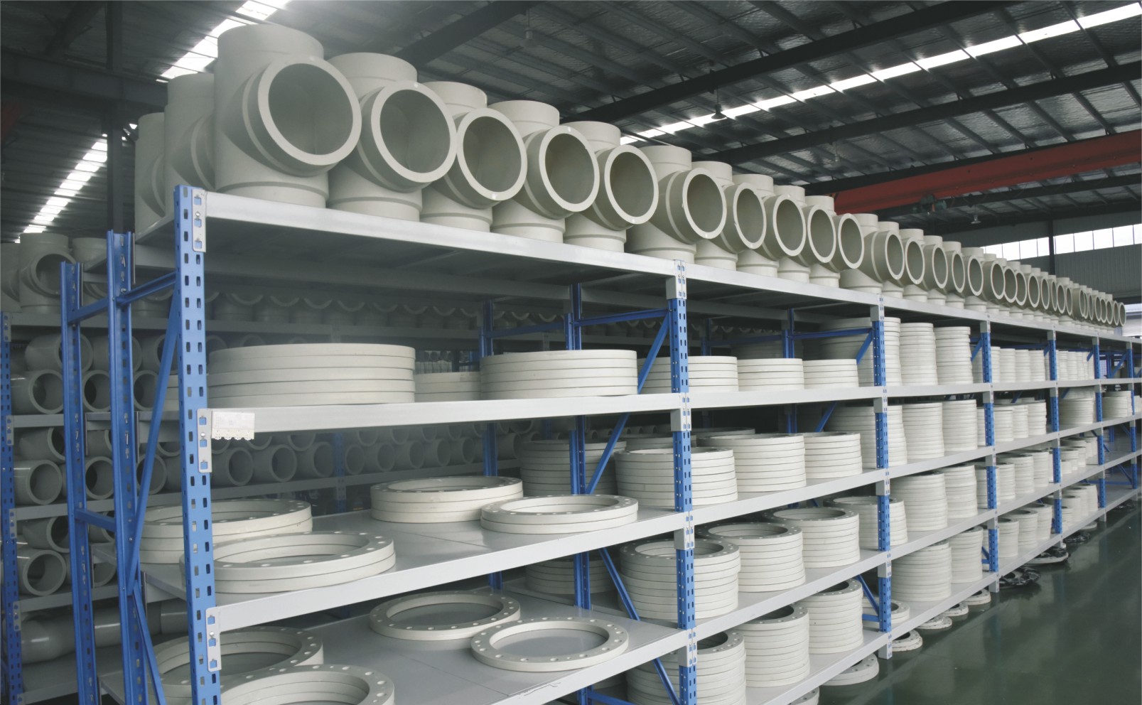
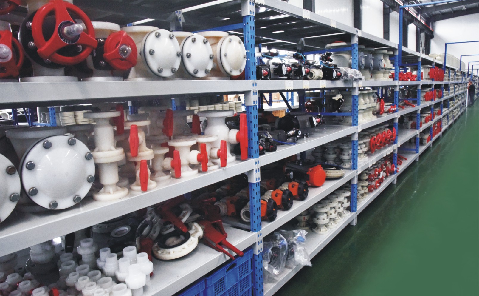
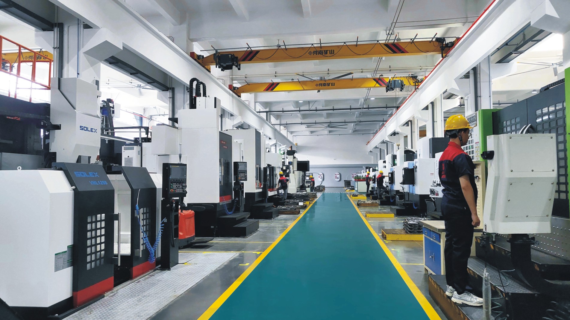
Factory Environment
Why Choose Us
Superior Quality
Our valves are produced from high-grade materials and subjected to strict quality inspections to guarantee dependable performance in challenging industrial environments.
Advanced Technology
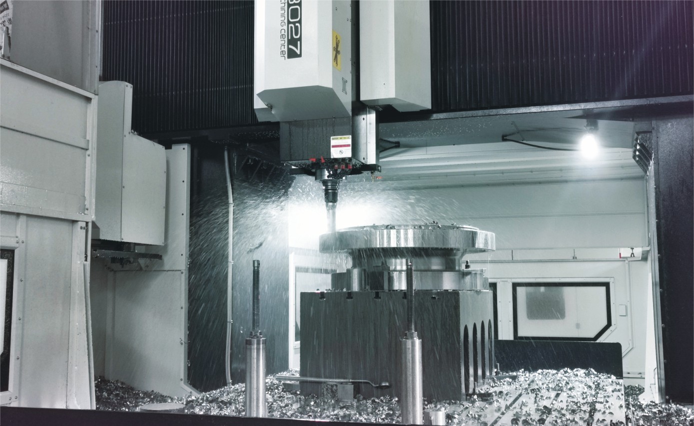
With cutting-edge CNC machining systems and high-precision manufacturing equipment, we ensure valves are made with outstanding accuracy and uniformity.
Competitive Pricing
By streamlining production processes and sourcing materials in bulk, we provide premium-quality valves at competitive prices while maintaining excellent standards.
Expert Support
Our skilled technical team offers full support from product selection through after-sales service, helping ensure the best valve performance for your application.