Application Temperature Range Table
| Materials | Medium temperature (°C) |
|---|
| RPP | -14°C ~ +90°C |
| UPVC | -10°C ~ +70°C |
| PVDF | -40°C ~ +140°C |
| CPVC | -40°C ~ +95°C |
Features
• Since the establishment of the company, the first plastic diaphragm valve was produced in 1979, and certification from the Ministry of Chemical Industry was obtained in 1983.
• High-quality sealing materials are used for diaphragm valve sealing, featuring low compression deformation and a double-layer diaphragm design to achieve optimal sealing performance.
• The design improves the diaphragm valve structure to ensure even pressure distribution, reducing the valve’s closing torque.
• Processing and assembly are strictly controlled, resulting in more stable and accurate flow regulation.
• The diaphragm valve structure has no dead zones, does not contaminate the medium, offers strong corrosion resistance, eliminates packing wear, and provides excellent internal sealing performance.
Advantage
• Optional double-layer diaphragm with excellent corrosion resistance;
• Good maintainability, allowing maintenance directly on the pipeline;
• The sealing performance of the diaphragm valve degrades gradually rather than suddenly, enabling planned maintenance cycles without affecting production continuity;
• Has a certain tolerance to slurry (better than ball valves, but not as good as clamp valves);
• Suitable for gaseous or volatile media;
• Can be used for flow regulation;
• Almost no dead zones, self-cleaning, and high cleanliness.
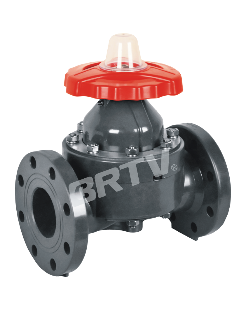
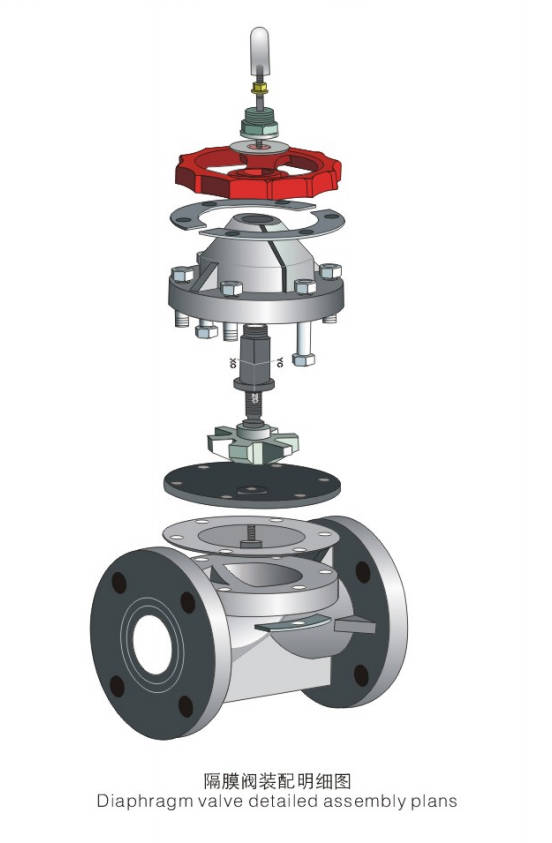
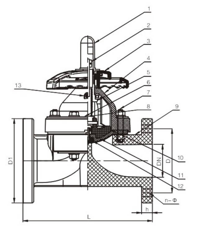
Parts & Material
| No. | Parts | Materials |
|---|
| 1 | Gauge cover | PC |
| 2 | Stud nut | Steel, stainless steel |
| 3 | Hand wheel | ABS, FRPP |
| 4 | Bonnet | HR-PP, FRPP, PPH, UPVC, CPVC, PVDF |
| 5 | Sleeve | Cast iron, copper alloy |
| 6 | Board | Plastic-coated steel, stainless steel |
| 7 | Bolts and nuts | Steel, stainless steel |
| 8 | Stem | Steel, stainless steel, copper alloy |
| 9 | Body | FRPP, PPH, UPVC, CPVC, PVDF |
| 10 | Compressor | PVDF, CPVC, cast iron |
| 11 | Cushion | EPDM |
| 12 | Diaphragm | EPDM, FPM, FEP, PFA, PTFE |
| 13 | Grease nipple | Copper alloy, stainless steel (DN80–300 used only) |
Cv Reference valve
| DN | Cv value |
|---|
| 15 | 5.4 |
| 20 | 6.3 |
| 25 | 7.2 |
| 32 | 8.1 |
| 40 | 23.4 |
| 50 | 43.2 |
| 65 | 76.5 |
| 80 | 103.5 |
| 100 | 166.5 |
| 125 | 270 |
| 150 | 360 |
| 200 | 630 |
| 250 | 900 |
| 300 | 900 |
Diaphragm valve working pressure and working temperature gauge (MPa)
| DN | FRPP 20°C | FRPP 60°C | FRPP 90°C | PPH 20°C | PPH 60°C | PPH 85°C | UPVC 20°C | UPVC 50°C | CPVC 20°C | CPVC 60°C | CPVC 85°C | PVDF 20°C | PVDF 60°C | PVDF 90°C | PVDF 120°C |
|---|
| 15 | 1.0 | 0.8 | 0.3 | 1.0 | 0.7 | 0.3 | 1.0 | 0.5 | 1.0 | 0.8 | 0.3 | 1.0 | 1.0 | 0.6 | 0.4 |
| 20 | 1.0 | 0.8 | 0.3 | 1.0 | 0.7 | 0.3 | 1.0 | 0.5 | 1.0 | 0.8 | 0.3 | 1.0 | 1.0 | 0.6 | 0.4 |
| 25 | 1.0 | 0.8 | 0.3 | 1.0 | 0.7 | 0.3 | 1.0 | 0.5 | 1.0 | 0.8 | 0.3 | 1.0 | 1.0 | 0.6 | 0.4 |
| 32 | 1.0 | 0.6 | 0.3 | 1.0 | 0.5 | 0.3 | 1.0 | 0.5 | 1.0 | 0.6 | 0.3 | 1.0 | 1.0 | 0.6 | 0.4 |
| 40 | 1.0 | 0.6 | 0.3 | 1.0 | 0.5 | 0.3 | 1.0 | 0.5 | 1.0 | 0.6 | 0.3 | 1.0 | 1.0 | 0.6 | 0.4 |
| 50 | 1.0 | 0.6 | 0.3 | 1.0 | 0.5 | 0.3 | 1.0 | 0.5 | 1.0 | 0.6 | 0.3 | 1.0 | 1.0 | 0.6 | 0.4 |
| 65 | 1.0 | 0.5 | 0.2 | 1.0 | 0.4 | 0.2 | 1.0 | 0.4 | 1.0 | 0.5 | 0.2 | 1.0 | 1.0 | 0.5 | 0.3 |
| 80 | 1.0 | 0.5 | 0.2 | 1.0 | 0.4 | 0.2 | 1.0 | 0.4 | 1.0 | 0.5 | 0.2 | 1.0 | 1.0 | 0.5 | 0.3 |
| 100 | 1.0 | 0.5 | 0.2 | 1.0 | 0.4 | 0.2 | 1.0 | 0.4 | 1.0 | 0.5 | 0.2 | 1.0 | 0.8 | 0.5 | 0.3 |
| 125 | 0.5 | 0.3 | 0.15 | 0.5 | 0.2 | 0.15 | 0.6 | 0.3 | 0.6 | 0.3 | 0.2 | 0.6 | 0.6 | 0.4 | 0.2 |
| 150 | 0.5 | 0.3 | 0.15 | 0.5 | 0.2 | 0.15 | 0.6 | 0.3 | 0.6 | 0.3 | 0.2 | 0.6 | 0.6 | 0.4 | 0.2 |
| 200 | 0.3 | 0.2 | 0.1 | 0.3 | 0.15 | 0.1 | 0.3 | 0.1 | 0.3 | 0.2 | 0.1 | 0.4 | 0.4 | 0.2 | 0.1 |
| 250 | 0.3 | 0.2 | 0.1 | 0.3 | 0.15 | 0.1 | 0.3 | 0.1 | 0.3 | 0.2 | 0.1 | 0.3 | 0.3 | 0.2 | 0.1 |
| 300 | 0.3 | 0.2 | 0.1 | 0.3 | 0.15 | 0.1 | 0.3 | 0.1 | 0.3 | 0.2 | 0.1 | 0.3 | 0.3 | 0.2 | 0.1 |
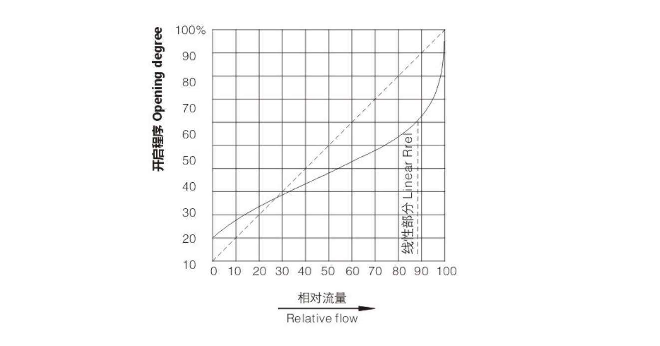
Flow characteristic curve of diaphragm valve
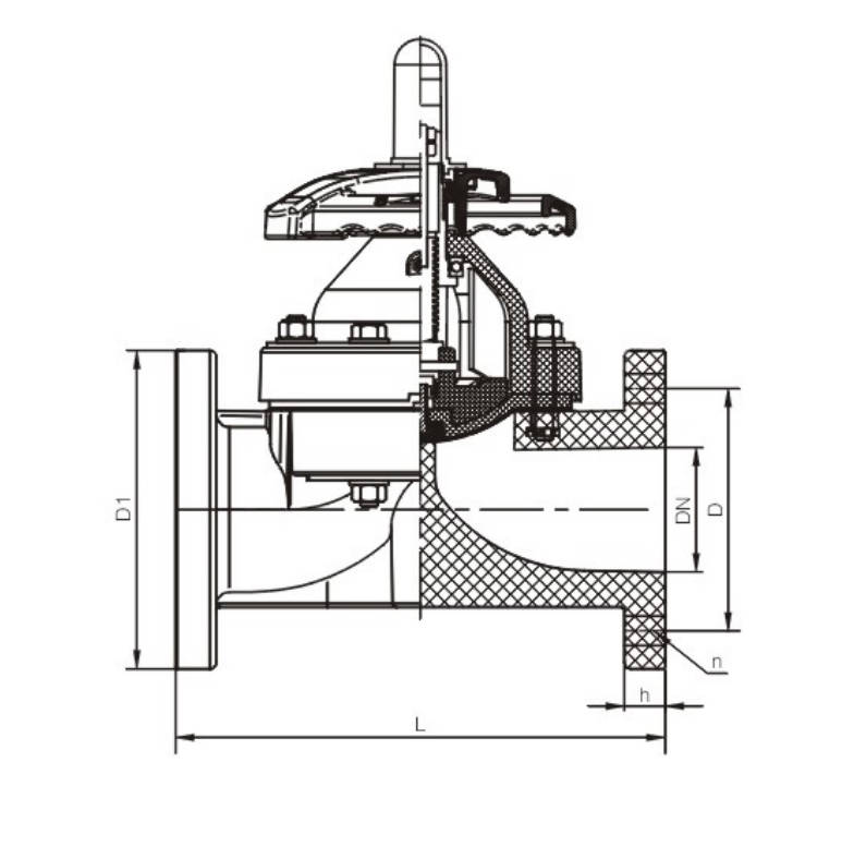
Dimensions Table
| DN | D1 HG/DIN | D1 JIS | D1 ANSI | D HG/DIN | D JIS | D ANSI | L HG/DIN | L JIS | L ANSI | n | h HG/DIN | h JIS | h ANSI | Φ HG/DIN | Φ JIS | Φ ANSI |
|---|
| 15 | 95 | 95 | 95 | 65 | 70 | 60 | 125 | 110 | 110 | 14 | 4 | 4 | 4 | 14 | 15 | 16 |
| 20 | 105 | 100 | 100 | 75 | 75 | 70 | 135 | 120 | 120 | 16 | 4 | 4 | 4 | 14 | 15 | 16 |
| 25 | 115 | 125 | 125 | 85 | 90 | 79 | 145/160 | 130 | 130 | 16 | 4 | 4 | 4 | 14 | 15 | 16 |
| 32 | 135 | 135 | 135 | 100 | 100 | 89 | 160/180 | 160 | 160 | 16 | 4 | 4 | 4 | 18 | 19 | 16 |
| 40 | 145 | 145 | 145 | 110 | 105 | 98 | 180 | 180 | 180 | 16 | 4 | 4 | 4 | 18 | 19 | 16 |
| 50 | 160 | 160 | 160 | 125 | 120 | 121 | 210/230 | 210 | 210 | 18 | 4 | 4 | 4 | 18 | 19 | 19 |
| 65 | 180 | 180 | 180 | 145 | 140 | 140 | 250 | 250 | 250 | 22 | 4 | 4 | 4 | 18 | 19 | 19 |
| 80 | 195 | 195 | 195 | 160 | 150 | 152 | 300 | 280 | 280 | 25 | 8 | 8 | 4 | 18 | 19 | 19 |
| 100 | 215 | 220 | 220 | 180 | 175 | 190 | 350 | 340 | 340 | 25 | 8 | 8 | 8 | 18 | 19 | 19 |
| 125 | 255 | 255 | 255 | 210 | 210 | 216 | 405 | 405 | 405 | 30 | 8 | 8 | 8 | 18 | 19 | 22 |
| 150 | 280 | 280 | 280 | 240 | 240 | 241 | 460 | 460/480 | 460/480 | 30 | 8 | 8 | 8 | 22 | 23 | 22 |
| 200 | 340 | 340 | 340 | 295 | 290 | 298 | 575 | 575 | 575 | 38 | 8 | 12 | 8 | 22 | 23 | 22 |
| 250 | 395 | 395 | 395 | 350 | 355 | 362 | 685 | 685 | 685 | 38 | 12 | 12 | 12 | 22 | 25 | 26 |
| 300 | 480 | 480 | 480 | 400 | 400 | 432 | 790 | 790 | 790 | 40 | 12 | 16 | 12 | 22 | 25 | 26 |
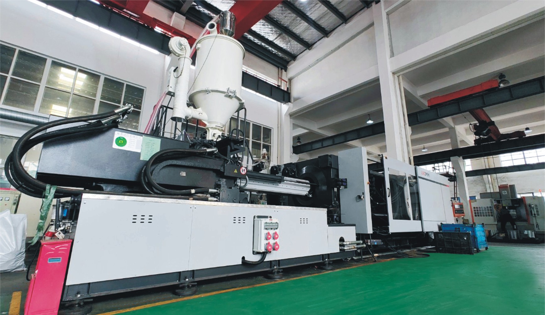
Manufacturing Process
Step 1: Order and Design
Confirm the customer’s requirements, including size, pressure rating, connection type, body material, and diaphragm material. Based on the application conditions, the design team prepares drawings and technical specifications for the A Type Diaphragm Valve to ensure the valve structure meets process and sealing requirements.
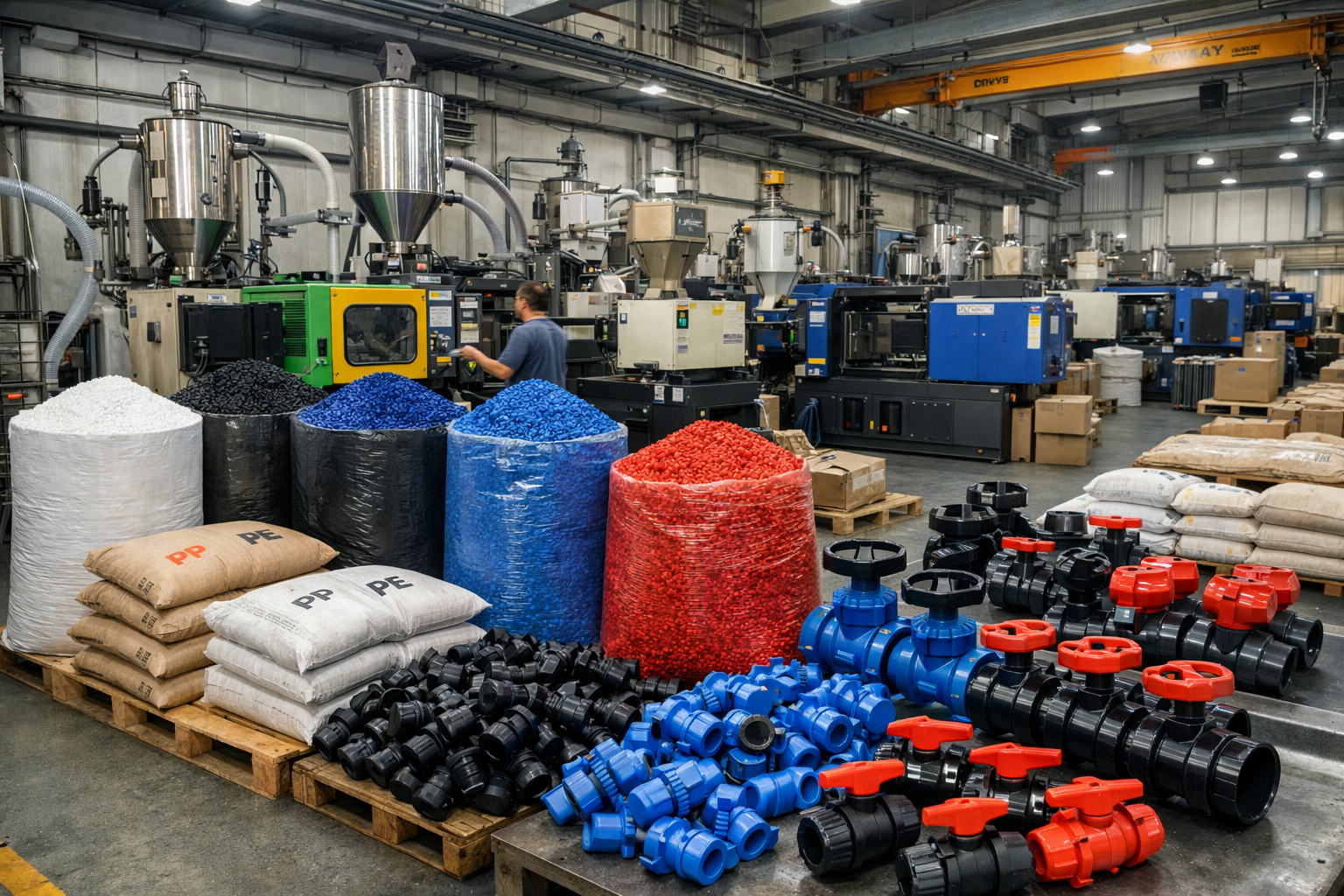
Step 2: Raw Material Preparation & Molding
Select qualified raw materials such as stainless steel, cast iron, or ductile iron for the valve body, and suitable rubber or PTFE for the diaphragm. The body blank of the A Type Diaphragm Valve is produced through casting, forging, or molding according to the design and production standard.
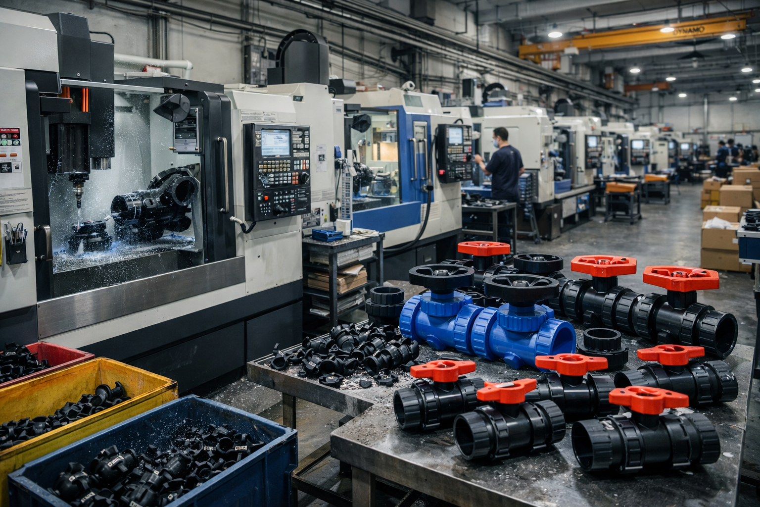
Step 3: Machining
Carry out precision machining on the valve body, bonnet, stem, and connection ends, including turning, milling, drilling, tapping, and sealing surface finishing. During this stage, the key dimensions of the A Type Diaphragm Valve are strictly controlled to guarantee assembly accuracy and smooth operation.
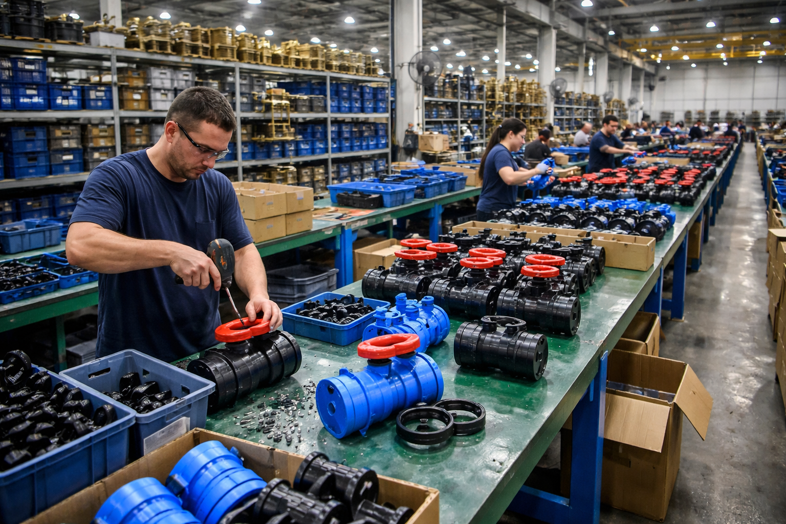
Step 4: Assembly
Assemble all finished components, including valve body, diaphragm, compressor, stem, handwheel, and bonnet. Special attention is paid to diaphragm positioning and fastening torque so that the A Type Diaphragm Valve can achieve reliable shut-off performance and long service life.
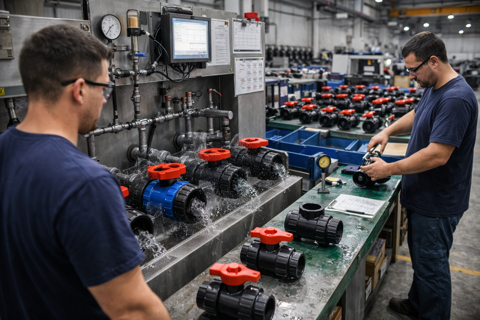
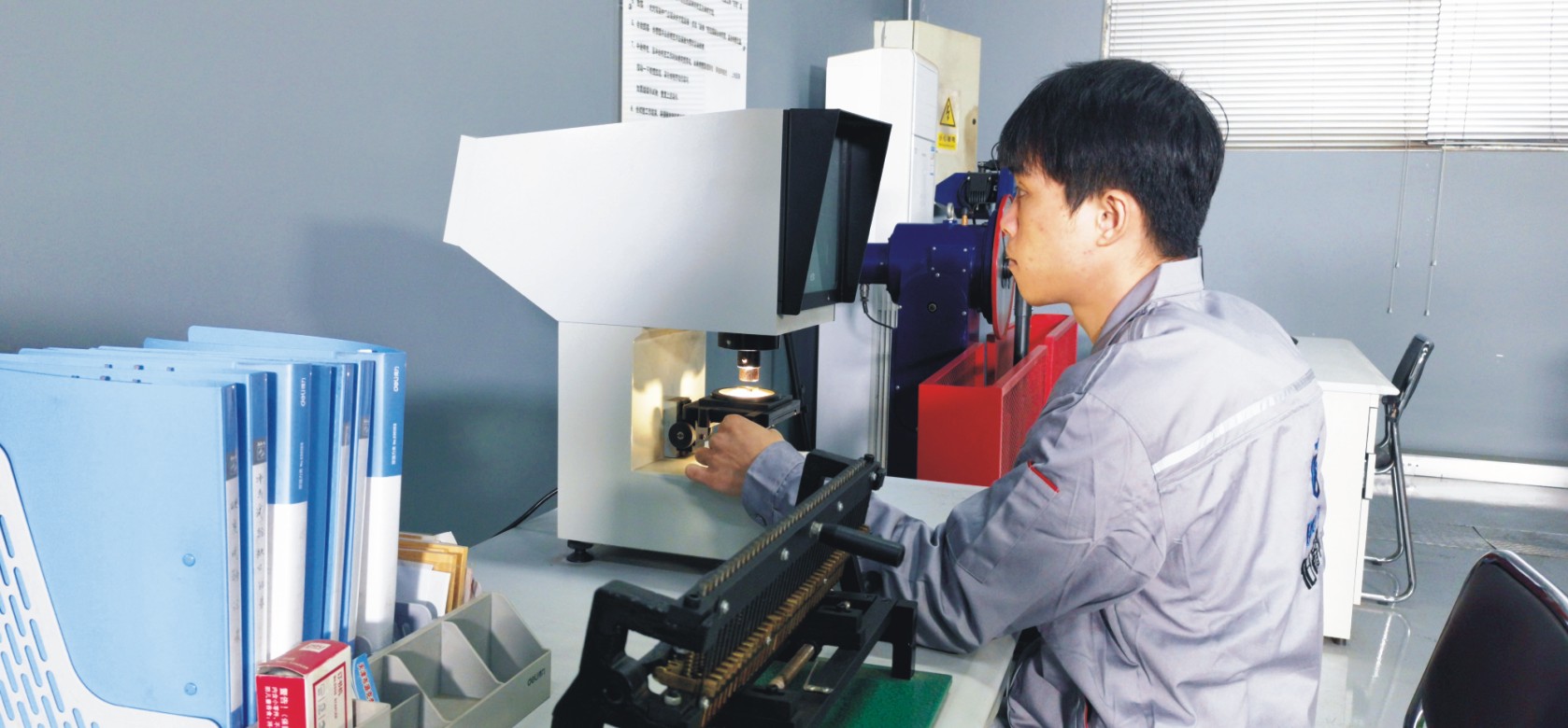
Step 5: Testing & Quality Assurance
Each A Type Diaphragm Valve undergoes pressure testing, sealing performance testing, operational testing, and visual inspection. Quality control staff also check critical dimensions, material certificates, and surface condition to ensure the valve complies with customer and industry standards.
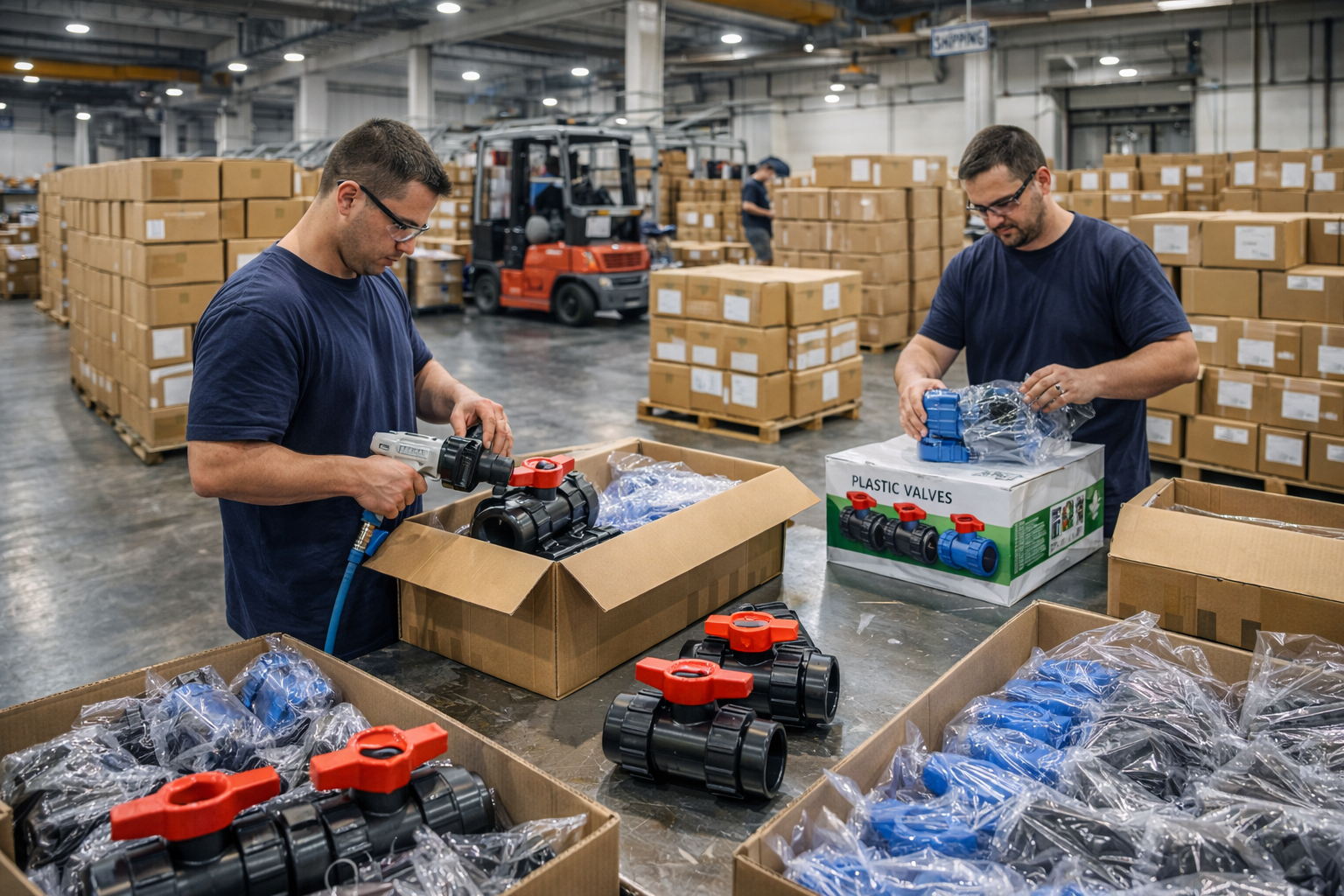
Step 6: Finishing, Packaging and Shipment
After final cleaning and surface treatment, the valve is marked, packed, and protected against damage during transportation. Then the products are arranged for shipment according to order quantity, delivery schedule, and export or domestic packaging requirements.
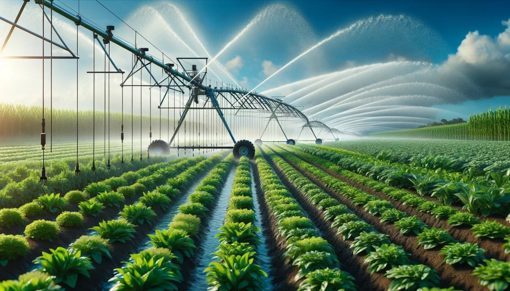
Applications
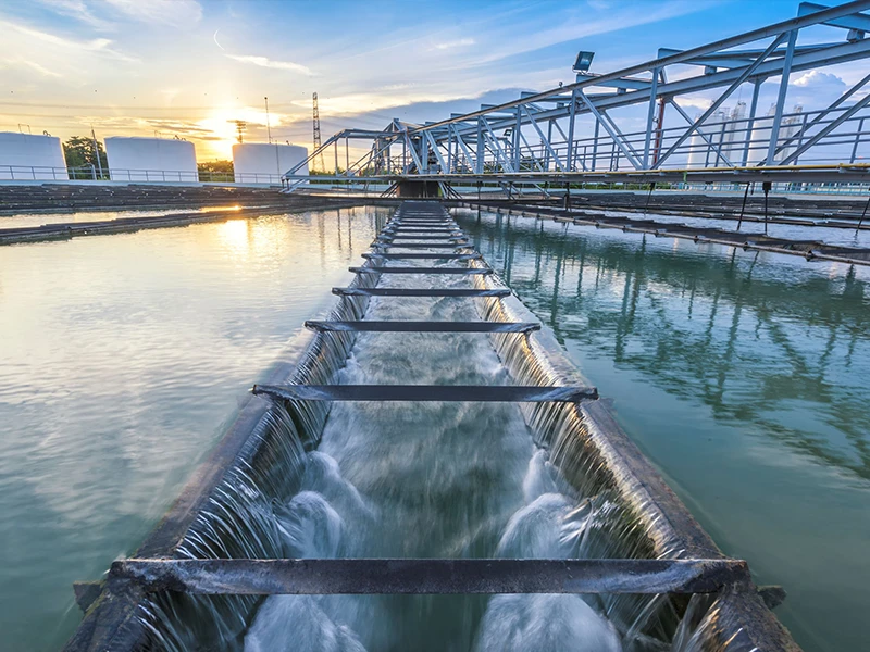
- Water Treatment: Regulating water flow and pressure.
- Chemical Industry: Controlling the flow of corrosive liquids.
- Power Industry: Controlling the circulation of cooling water.
- Healthcare: Controlling the flow of medications and liquids.
- Food and Beverage Industry: Controlling the flow of beverages to maintain quality.
- Industrial Gases: Controlling the flow of compressed air and other industrial gases.
These valves are widely used in:
Agriculture and Irrigation
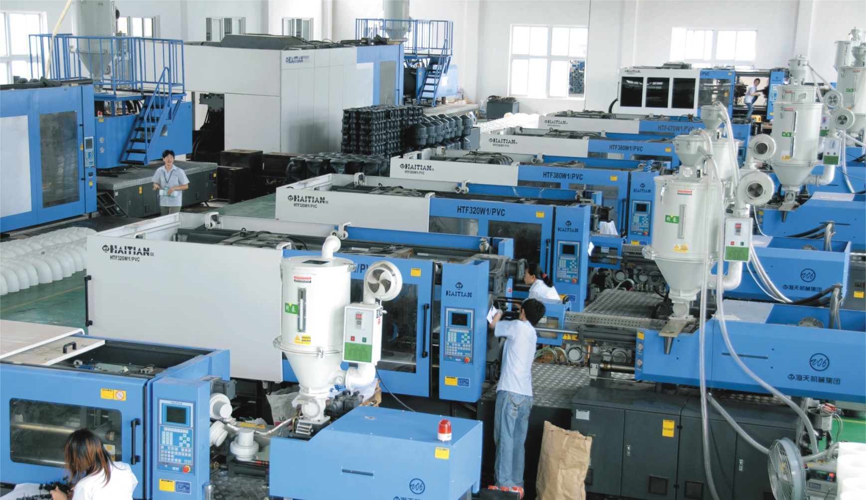
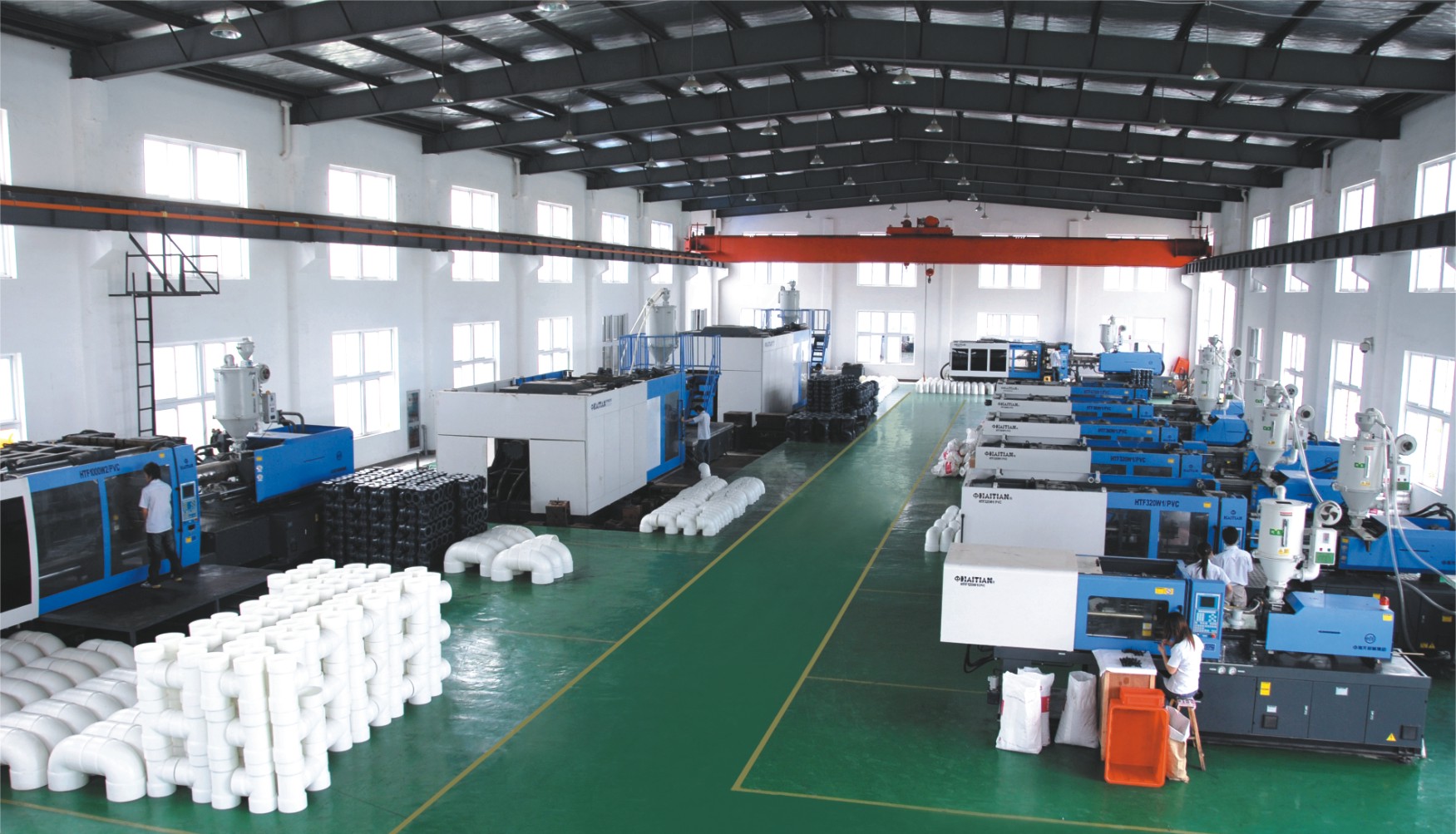
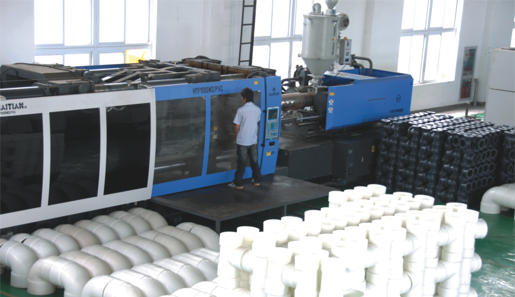
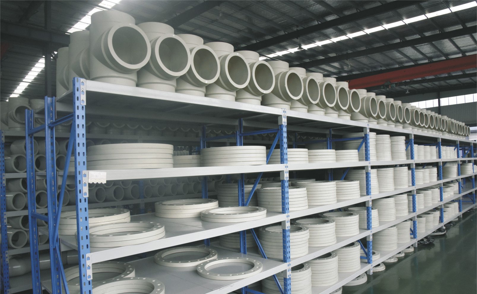
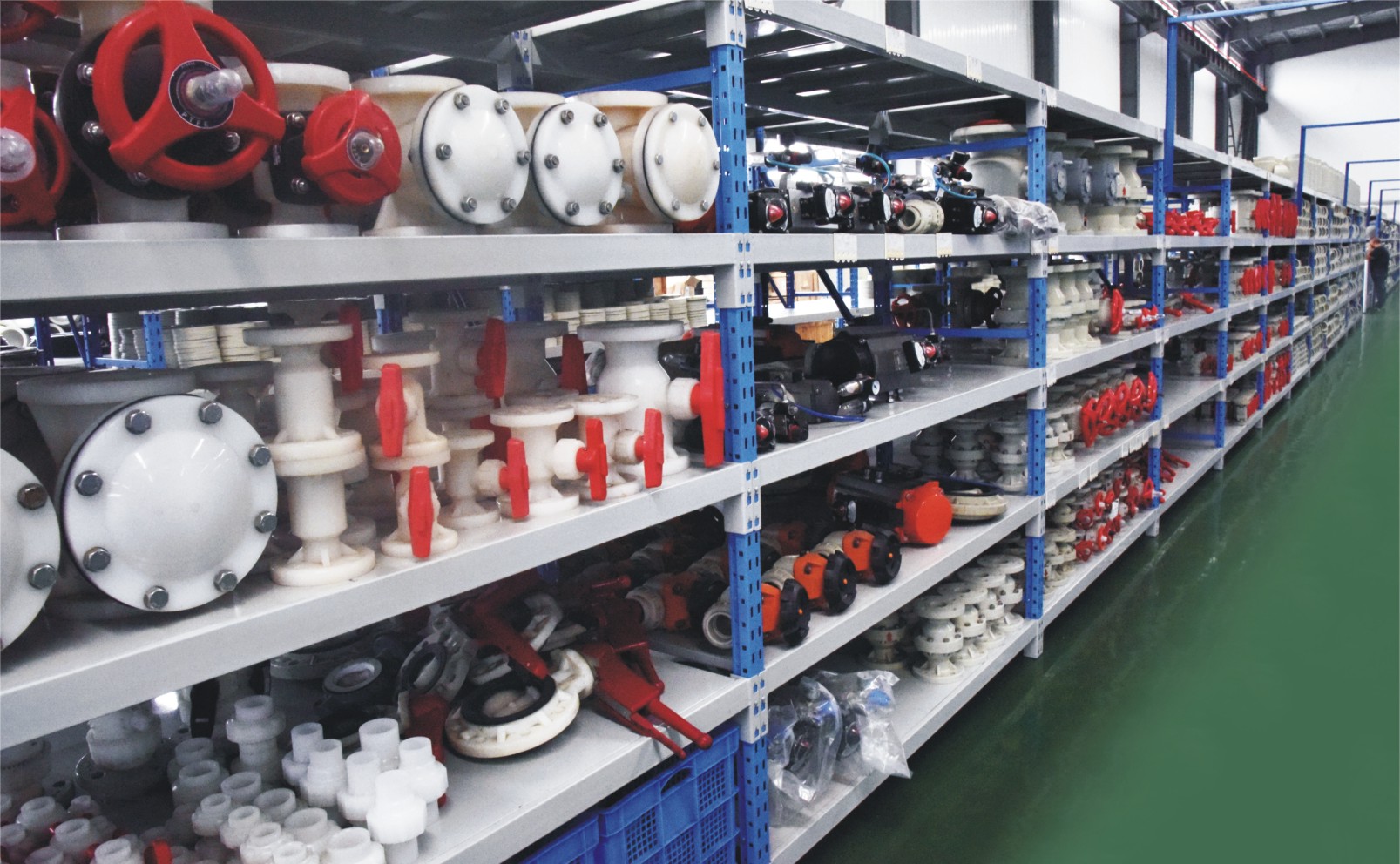
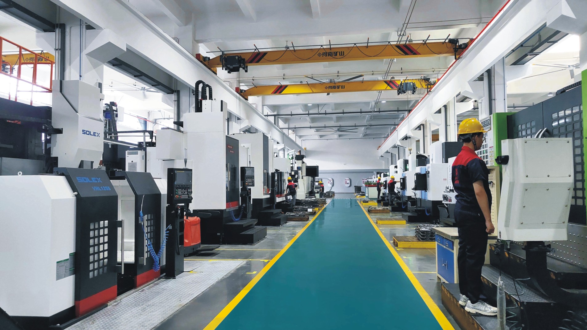
Factory Environment
Why Choose Us
Superior Quality
Our valves are produced from high-grade materials and subjected to strict quality inspections to guarantee dependable performance in challenging industrial environments.
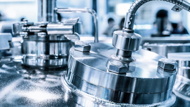
Advanced Technology
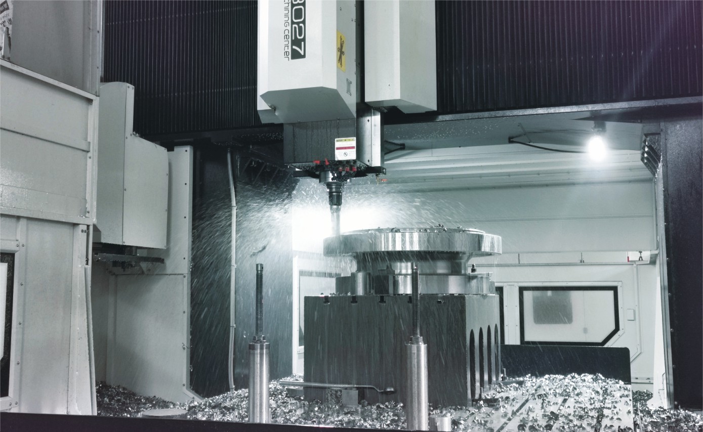
With cutting-edge CNC machining systems and high-precision manufacturing equipment, we ensure valves are made with outstanding accuracy and uniformity.
Competitive Pricing
By streamlining production processes and sourcing materials in bulk, we provide premium-quality valves at competitive prices while maintaining excellent standards.
Expert Support
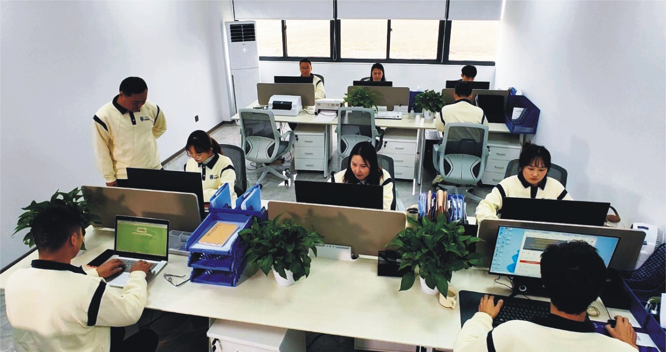
Our skilled technical team offers full support from product selection through after-sales service, helping ensure the best valve performance for your application.