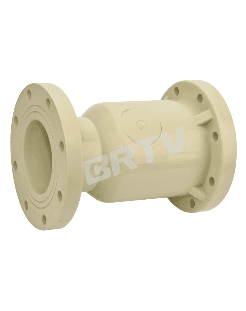
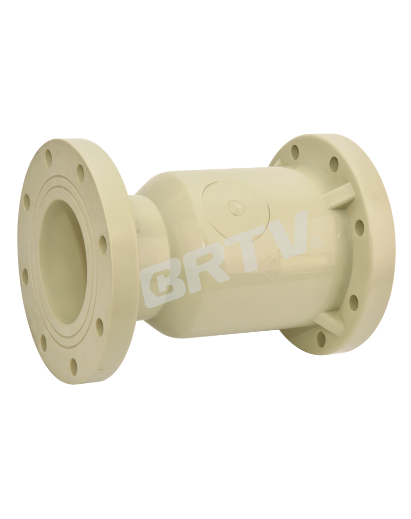
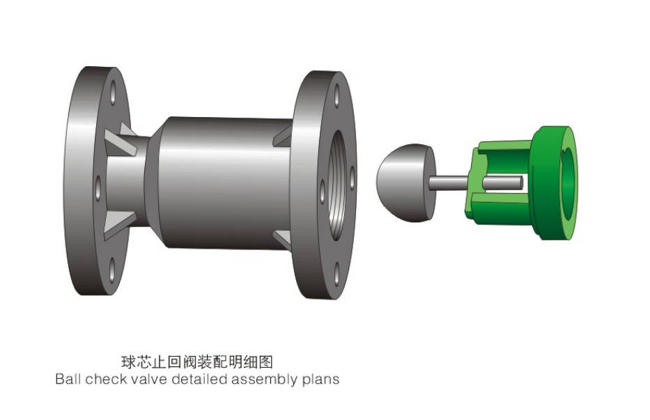
Ball Core Check Valve(Flanged)
Application Temperature Range Table
| Materials | Medium Temperature (°C) |
|---|
| RPP (Reinforced Polypropylene) | -14°C ~ +90°C |
| UPVC (Unplasticized Polyvinyl Chloride) | -10°C ~ +70°C |
| PVDF (Polyvinylidene Fluoride) | -40°C ~ +140°C |
| CPVC (Chlorinated Polyvinyl Chloride) | -40°C ~ +95°C |
Features
• Spherical core design ensures the valve is not easily clogged when the medium contains particles.
• Optional PTFE ball provides excellent sealing and corrosion resistance.
• The unique structural design reduces flow resistance.
• When installing the valve, follow the black arrow to indicate the flow direction of the medium.
Parts Material
| No. | Parts | Materials |
|---|
| 1 | Body | FRPP, PPH, UPVC, CPVC, PVDF |
| 2 | Ball | FRPP, PPH, UPVC, CPVC, PVDF, PTFE |
| 3 | Plastic Gasket | FRPP, PPH, UPVC, CPVC, PVDF (DN125–150 Used Only) |
| 4 | Seal | PTFE, EPDM, FPM |
| 5 | Plastic Gasket | FRPP, PPH, UPVC, CPVC, PVDF (DN125–150 Used Only) |
| 6 | O-ring | PTFE, EPDM, FPM (DN125–150 Used Only) |
| 7 | Inner Plug | FRPP, PPH, UPVC, CPVC, PVDF (DN125–DN150) |
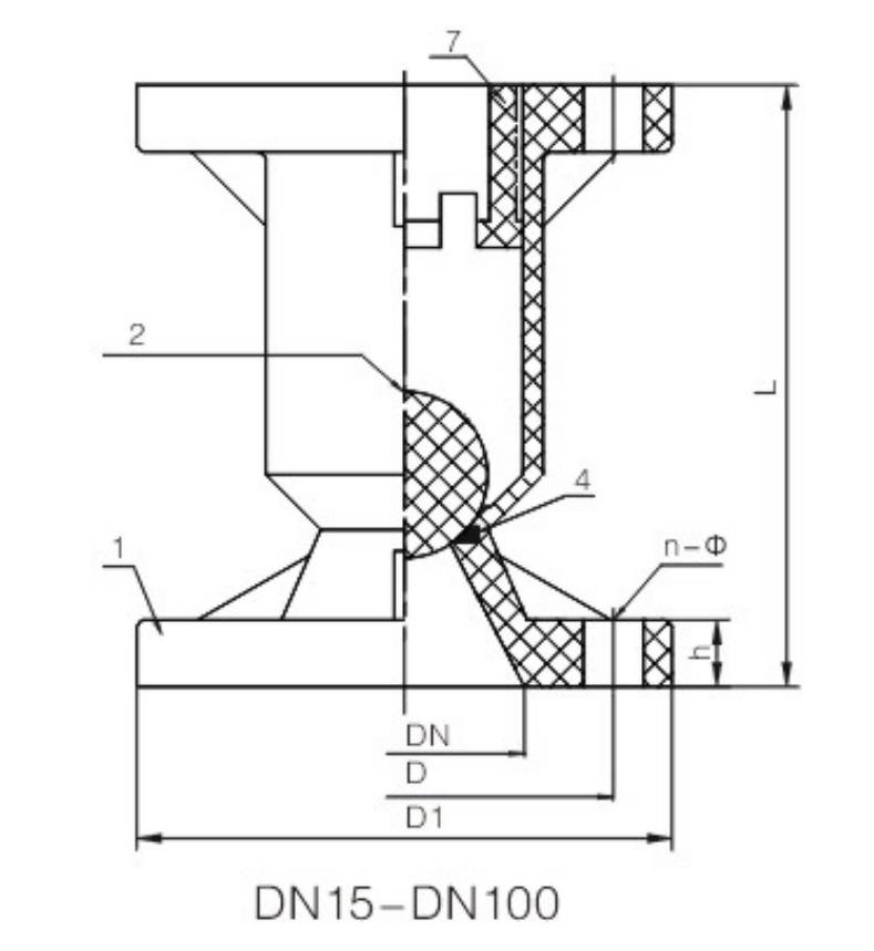
Dimension Table
| DN | D1 (mm) | D (DIN) | D (JIS) | D (ANSI) | L | H | n (HG/DIN) | n (JIS) | n (ANSI) | Φ (HG/DIN) | Φ (JIS) | Φ (ANSI) | Working Pressure (MPa) | Minimum Back Pressure (MPa) |
|---|
| 15 | 95 | 65 | 70 | 60 | 100 | 15 | 4 | 4 | 4 | 14 | 15 | 16 | 1.0 | 0.1 |
| 20 | 105 | 75 | 75 | 70 | 120 | 17 | 4 | 4 | 4 | 14 | 15 | 16 | 1.0 | 0.1 |
| 25 | 115 | 85 | 90 | 79 | 140 | 17 | 4 | 4 | 4 | 14 | 15 | 16 | 1.0 | 0.1 |
| 32 | 135 | 100 | 100 | 89 | 160 | 17 | 4 | 4 | 4 | 18 | 19 | 16 | 1.0 | 0.1 |
| 40 | 145 | 110 | 105 | 98 | 165 | 17 | 4 | 4 | 4 | 18 | 19 | 16 | 1.0 | 0.1 |
| 50 | 160 | 125 | 120 | 121 | 180 | 20 | 4 | 4 | 4 | 18 | 19 | 19 | 1.0 | 0.1 |
| 65 | 180 | 145 | 140 | 140 | 220 | 22 | 4 | 4 | 4 | 18 | 19 | 19 | 0.6 | 0.1 |
| 80 | 195 | 160 | 150 | 152 | 250 | 25 | 8 | 8 | 4* | 18 | 19 | 19 | 0.6 | 0.1 |
| 100 | 215 | 180 | 175 | 190 | 280 | 25 | 8 | 8 | 8 | 18 | 19 | 19 | 0.6 | 0.1 |
| 125 | 245 | 210 | 210 | 216 | 325 | 30 | 8 | 8 | 8 | 18 | 19 | 22 | 0.4 | 0.1 |
| 150 | 280 | 240 | 240 | 241 | 365 | 30 | 8 | 8 | 8 | 22 | 23 | 22 | 0.4 | 0.1 |
| 200 | 335 | 295 | 290 | 298 | 405 | 35 | 8 | 12* | 8 | 22 | 23 | 22 | 0.3 | 0.1 |
| 250 | 400 | 350 | 355 | 362 | 500 | 38 | 12 | 12 | 12 | 22 | 25 | 26 | 0.3 | 0.1 |
| 300 | 455 | 400 | 400 | 432 | 600 | 40 | 12 | 16* | 12 | 22 | 25 | 26 | 0.3 | 0.1 |
Ball Core Check Valve(Union)
Features
• Easy to install, requires minimal space, and is convenient to maintain.
• Suspended pipeline valves may be affected by water hammer and vibration, making the connecting threads prone to loosening and damage.
• Flexible connections are not recommended for harsh working conditions such as high temperature and strong corrosion.
Parts Material
| No. | Parts | Materials |
|---|
| 1 | Joints | PPH, UPVC, CPVC, PVDF |
| 2 | Union Nut | PPH, UPVC, CPVC, PVDF |
| 3 | O-ring | EPDM, FPM |
| 4 | Body | PPH, UPVC, CPVC, PVDF |
| 5 | Ball | PPH, UPVC, CPVC, PVDF, PTFE |
| 6 | Inside Plug | PPH, UPVC, CPVC, PVDF |
| 7 | Gasket | PPH, UPVC, CPVC, PVDF |
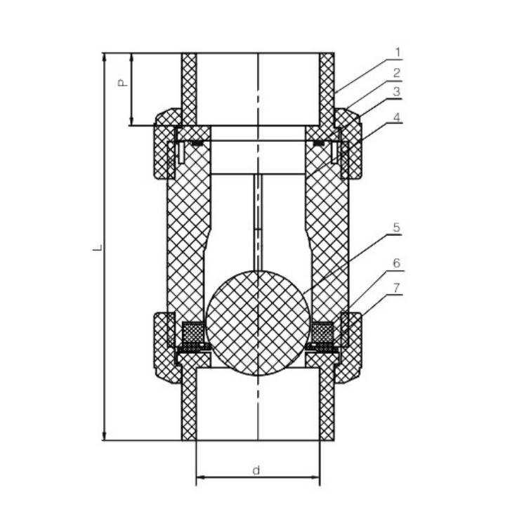
Dimension Table
| DN | Socket End (HG/DIN) | Socket End (JIS) | Socket End (ANSI) | Thread End (HG/DIN) | Thread End (JIS) | Thread End (ANSI) | L | P | Working Pressure (MPa) | Minimum Back Pressure (MPa) |
|---|
| 15 | 20 | 22 | 21.3 | Rc 1/2 | PT 1/2 | NPT 1/2 | 100 | 17 | 1.0 | 0.04 |
| 20 | 25 | 26 | 26.7 | Rc 3/4 | PT 3/4 | NPT 3/4 | 120 | 24 | 1.0 | 0.04 |
| 25 | 32 | 32 | 33.4 | Rc 1 | PT 1 | NPT 1 | 130 | 28 | 1.0 | 0.04 |
| 32 | 40 | 38 | 42.2 | Rc 1-1/4 | PT 1-1/4 | NPT 1-1/4 | 153 | 29 | 1.0 | 0.04 |
| 40 | 50 | 48 | 48.3 | Rc 1-1/2 | PT 1-1/2 | NPT 1-1/2 | 181 | 35 | 1.0 | 0.04 |
| 50 | 63 | 60 | 60.3 | Rc 2 | PT 2 | NPT 2 | 203 | 39 | 1.0 | 0.04 |
Manufacturing Process?
Step 1: Order and Design
Confirm parameters based on the customer’s operating conditions (pressure, temperature, and medium), complete the structural design of the ball core check valve—including ball core dimensions, sealing method, and flange standards—and generate production drawings.
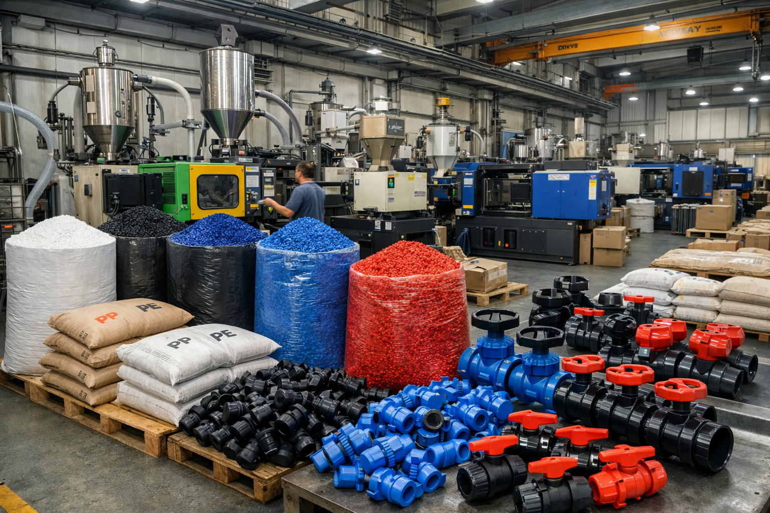
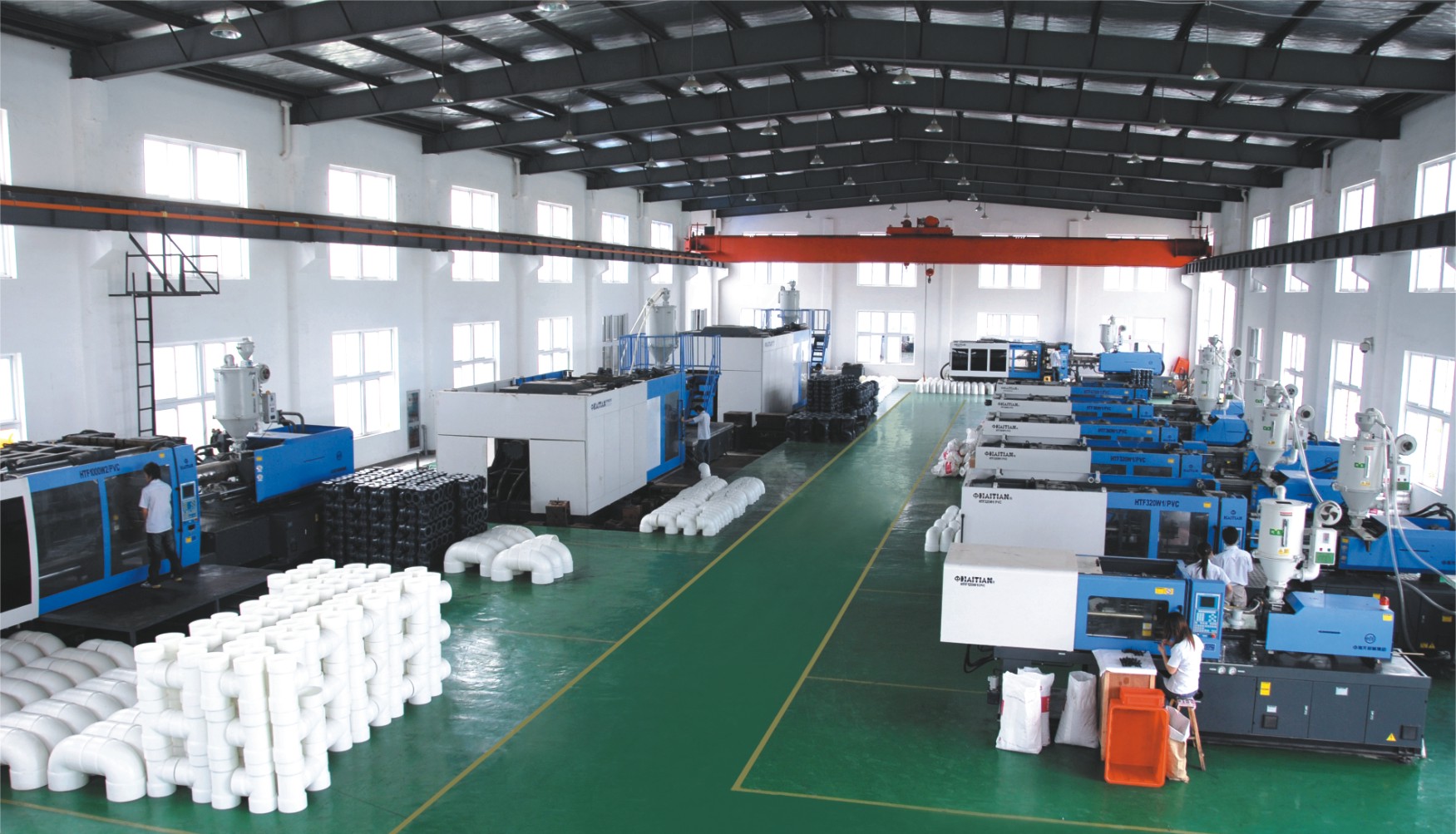
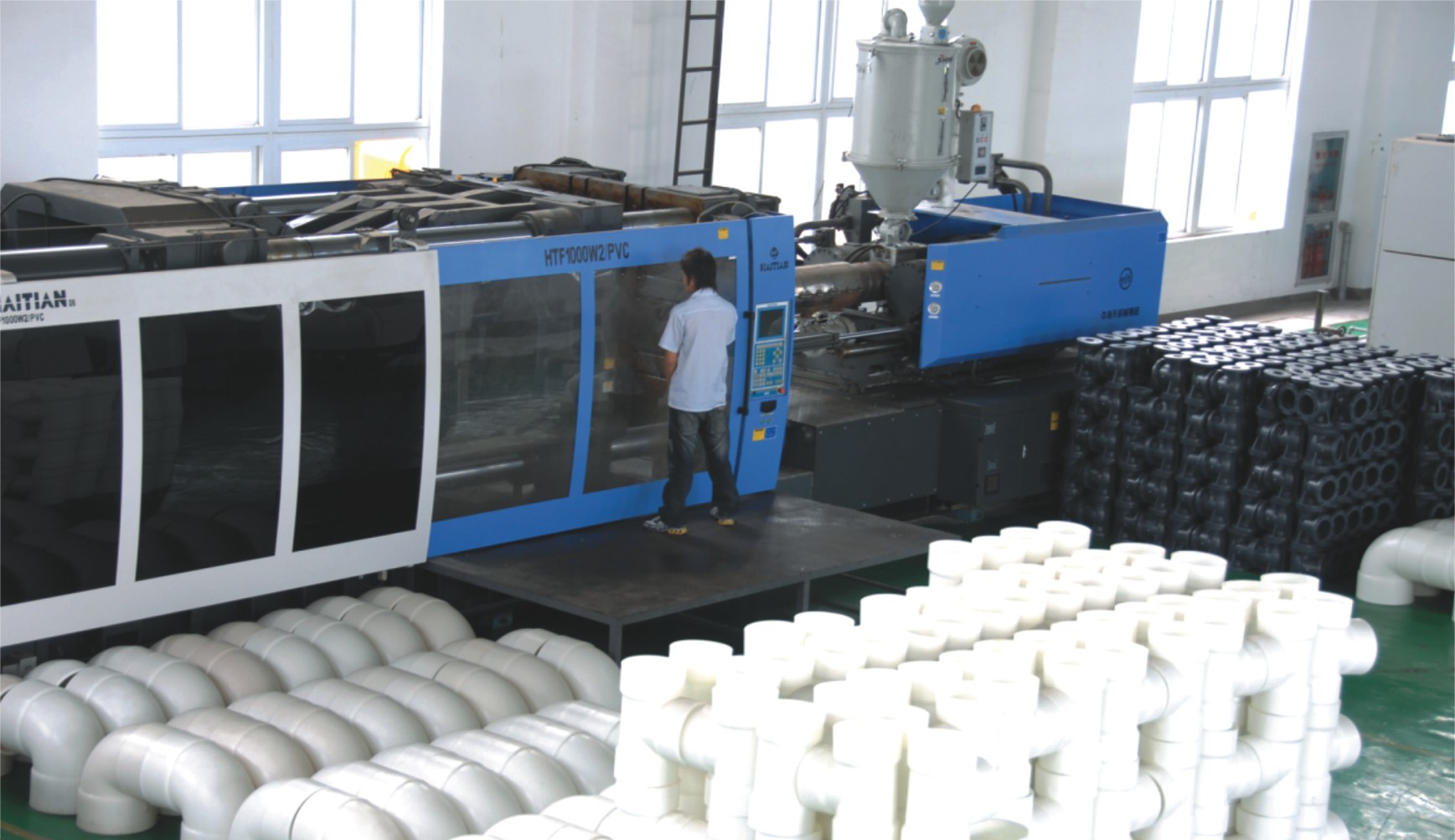
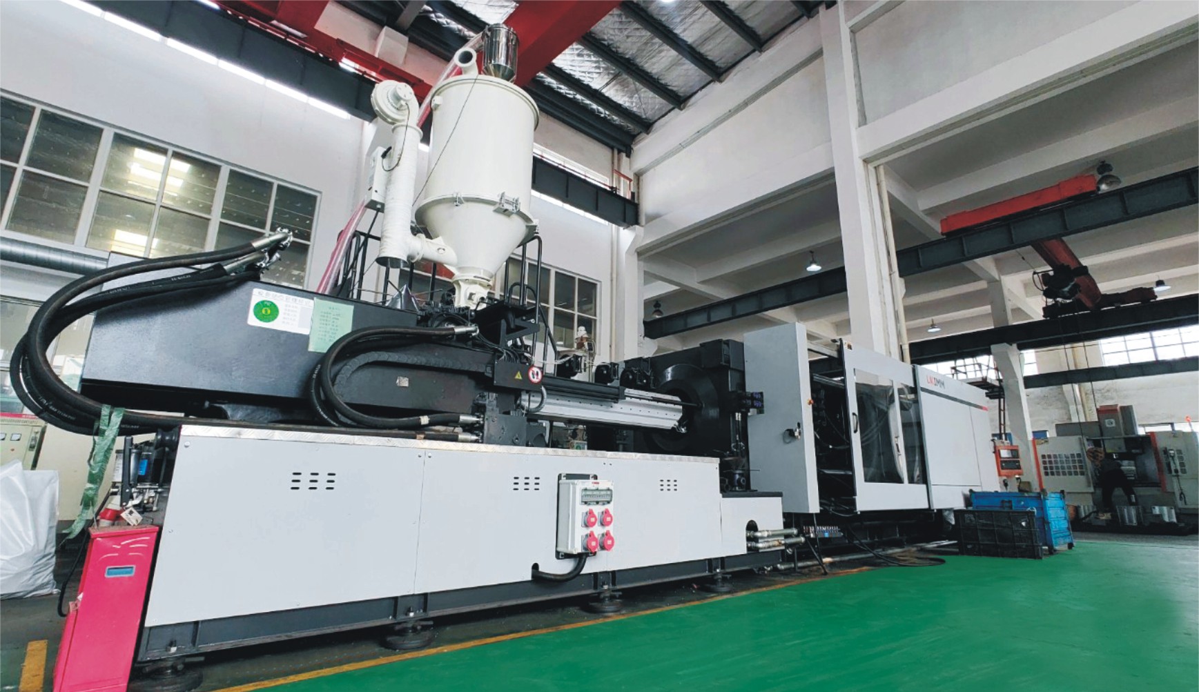
Step 2: Raw Material Preparation & Molding
Select suitable engineering plastics (such as PP, PVC, PVDF, etc.). After drying the raw materials, produce the valve body and ball core blanks for the ball core check valve via injection molding or compression molding.
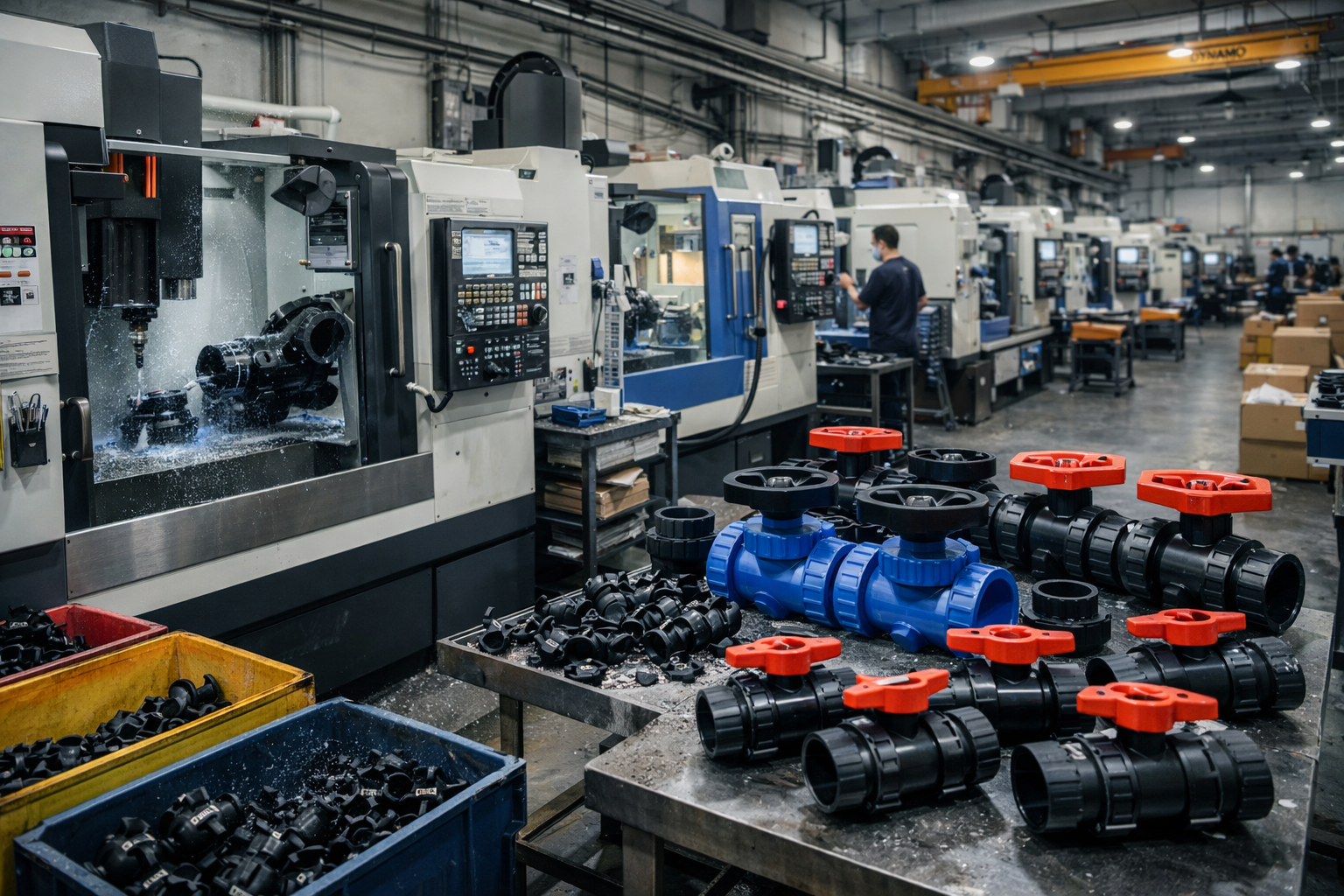
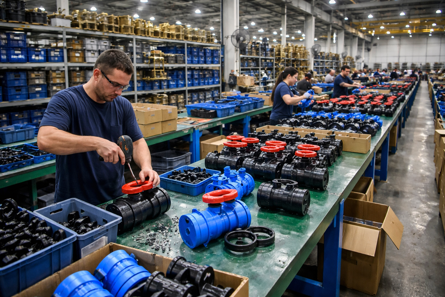
Step 3: Machining
Perform precision machining on the valve body, including the flange faces, sealing surfaces, and internal cavities, to ensure dimensional accuracy and concentricity, thereby meeting the sealing and flow path requirements of the ball core check valve.
Step 4: Assembly
Assemble the ball core, sealing rings, and valve body to ensure smooth ball core movement and reliable sealing, completing the overall assembly of the ball core check valve.
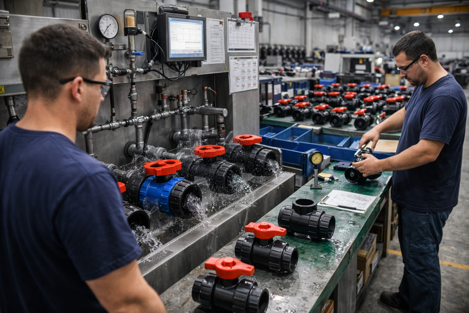
Step 5: Testing & Quality Assurance
Each ball core check valve undergoes seal testing, pressure testing, and opening/closing performance testing to ensure leak-free operation and compliance with relevant standards (such as ISO/DIN/ANSI).
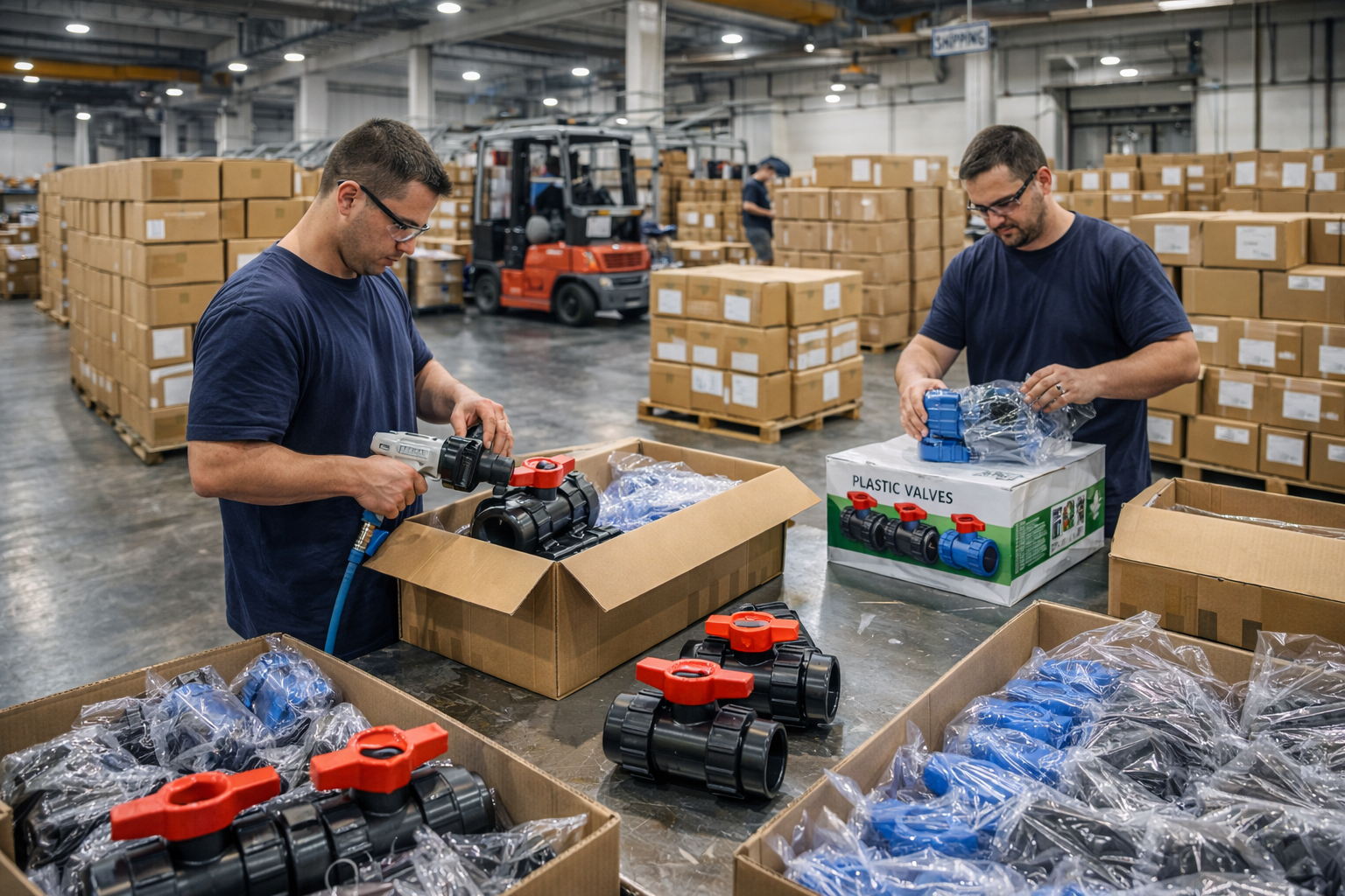
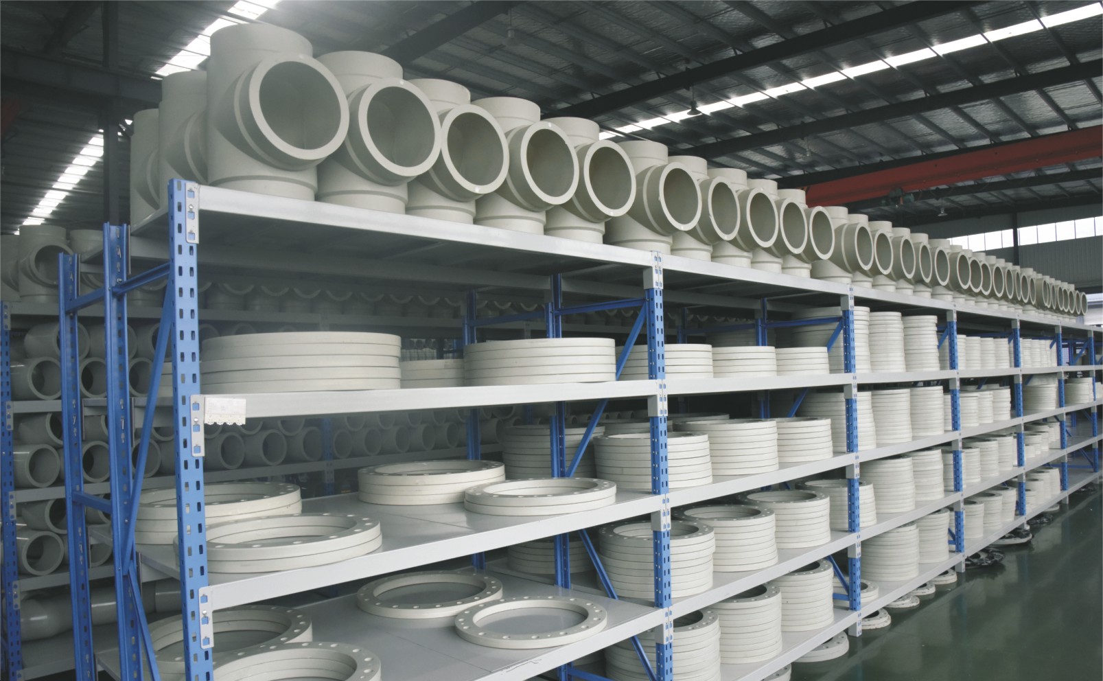
Step 6: Finishing, Packaging and Shipment
The valves undergo surface cleaning and marking, are packed in protective packaging to prevent damage during transport, and are then stored in the warehouse and prepared for shipment.
Applications
- Hydraulic systems in construction machinery: Used to protect steering mechanisms and working equipment
- Marine hydraulic circuits: Prevent seawater ingress and pressure fluctuations
- Hydraulic controls in agricultural machinery: Ensure reliable operation of actuators
- Industrial hydraulic branch lines: Isolate different pressure zones to prevent system interference
These valves are widely used in:
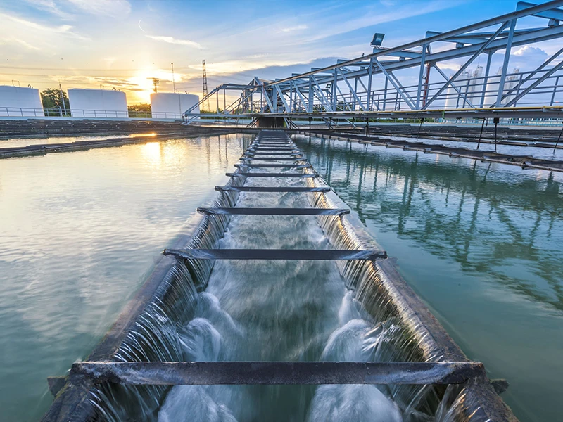
Agriculture and Irrigation
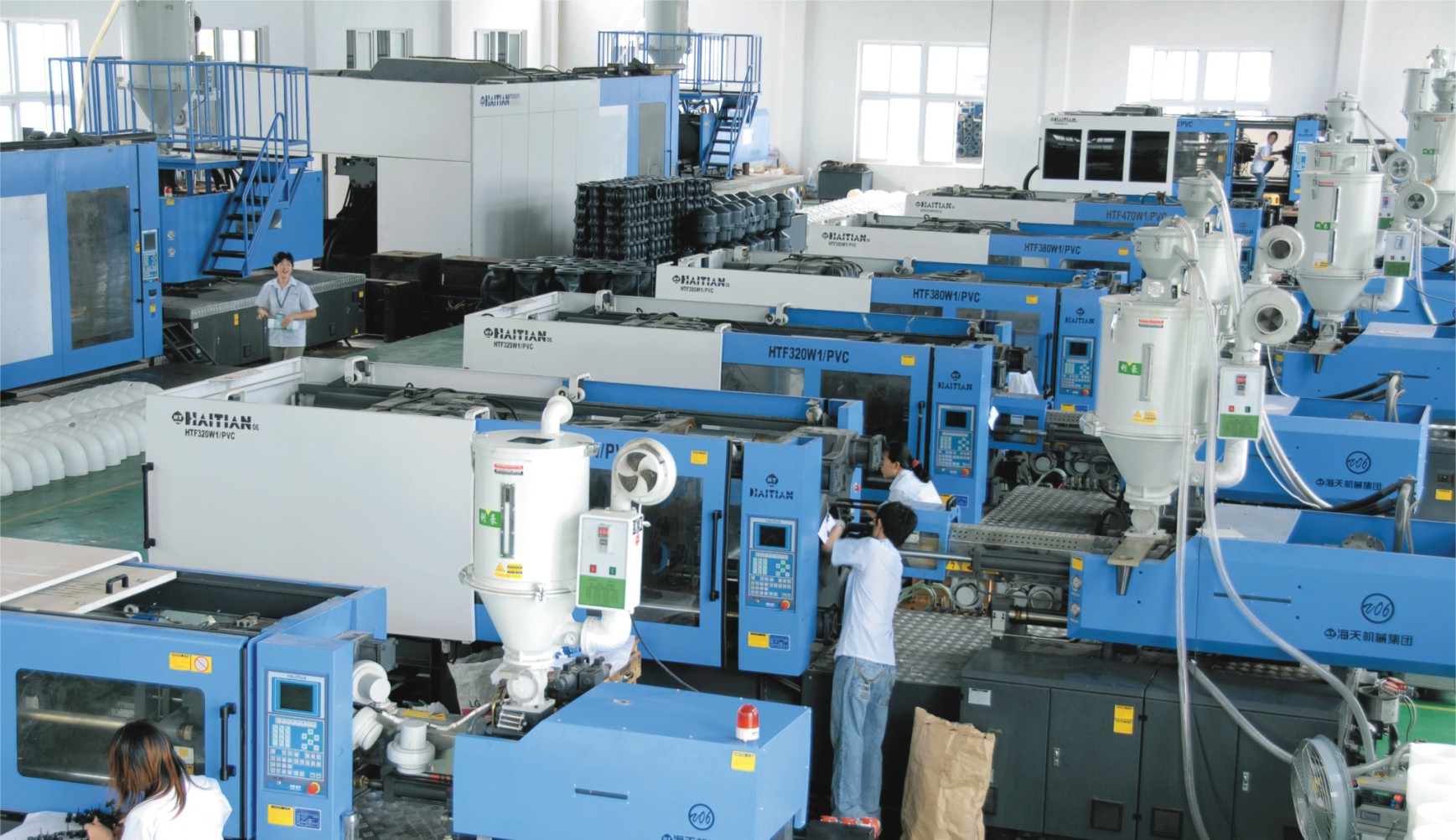
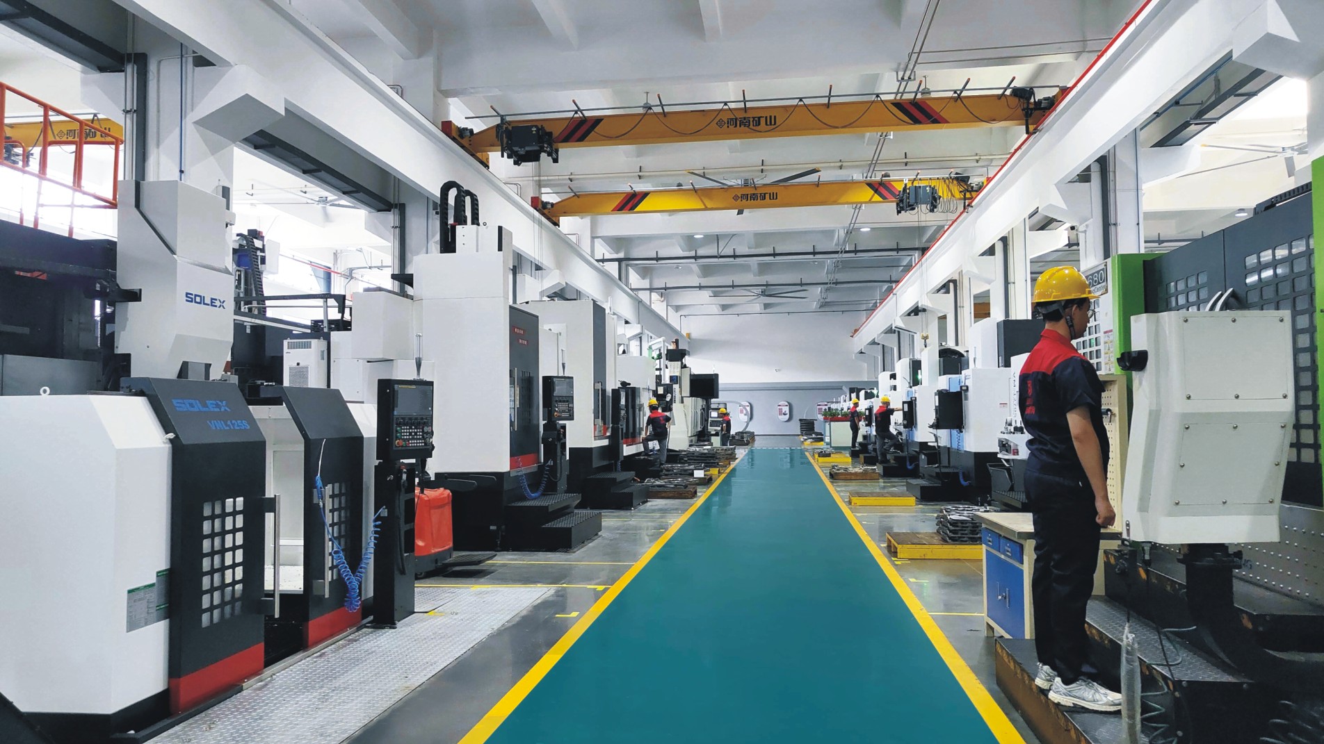
Factory Environment
Why Choose Us
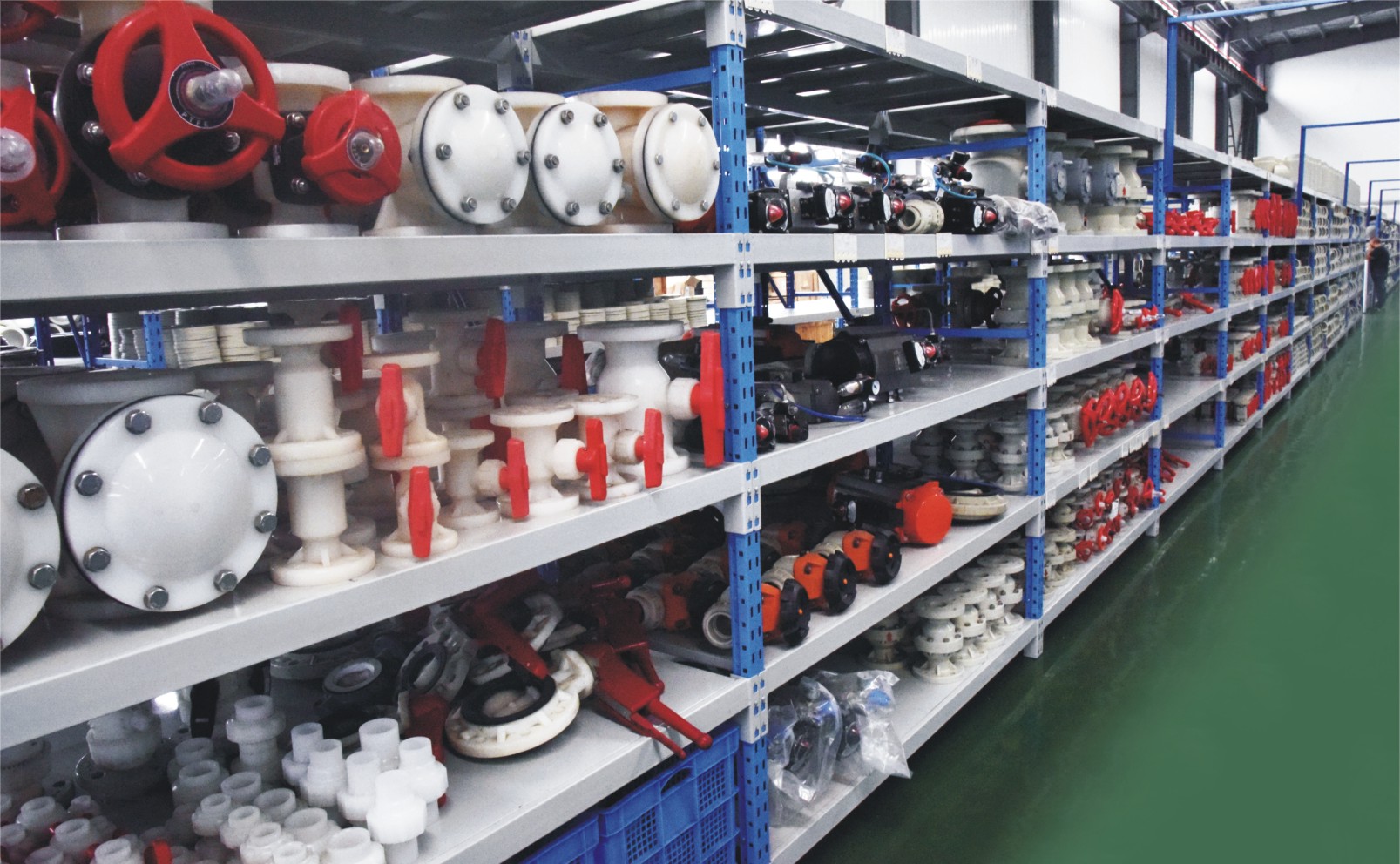
Superior Quality
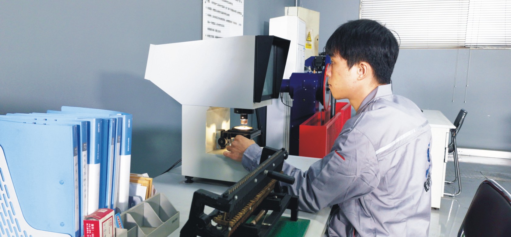
Our valves are produced from high-grade materials and subjected to strict quality inspections to guarantee dependable performance in challenging industrial environments.
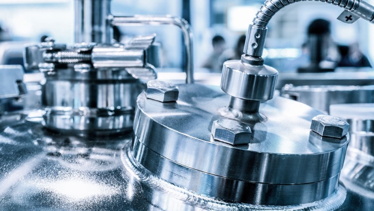
Advanced Technology
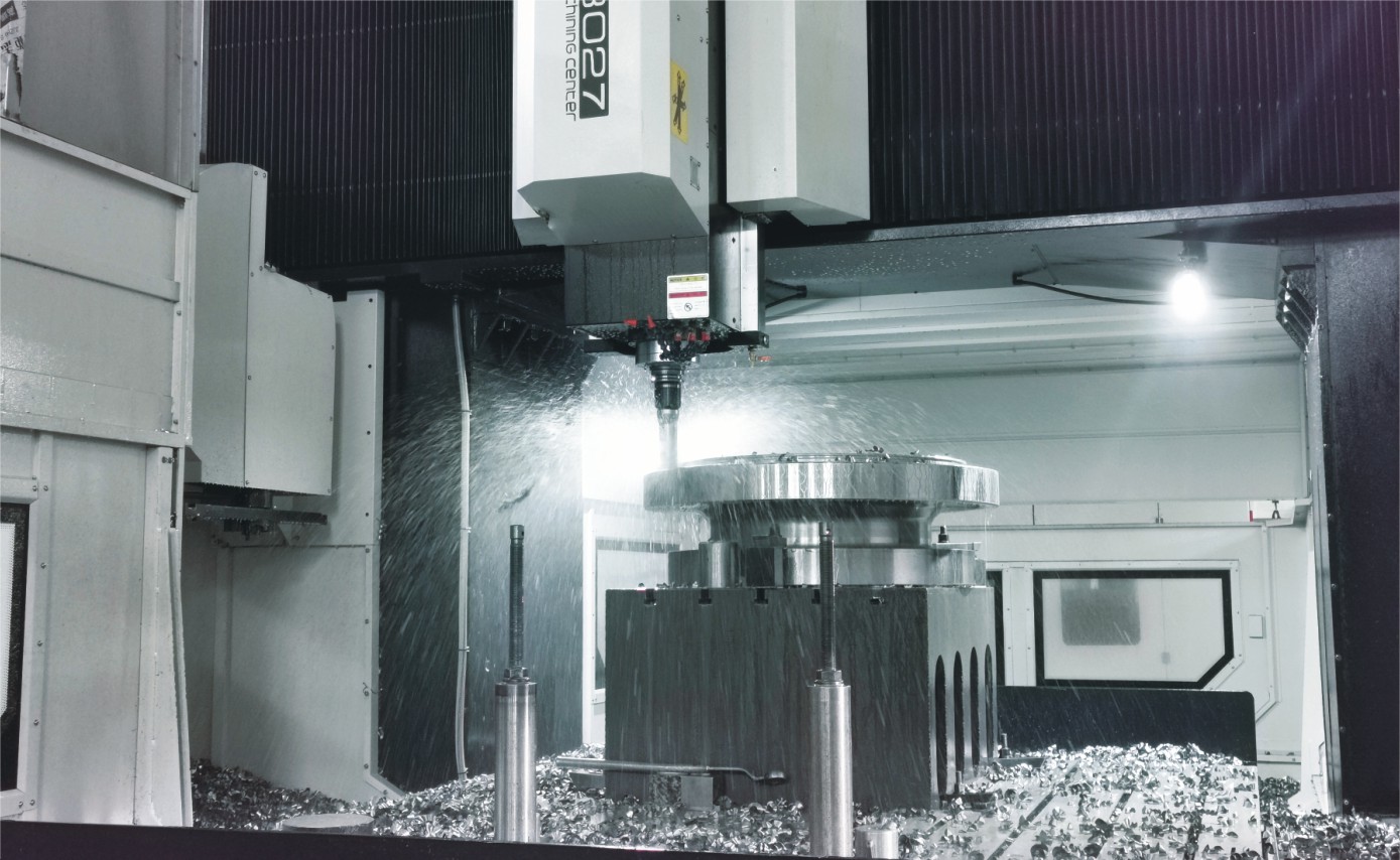
With cutting-edge CNC machining systems and high-precision manufacturing equipment, we ensure valves are made with outstanding accuracy and uniformity.
Competitive Pricing
By streamlining production processes and sourcing materials in bulk, we provide premium-quality valves at competitive prices while maintaining excellent standards.
Expert Support
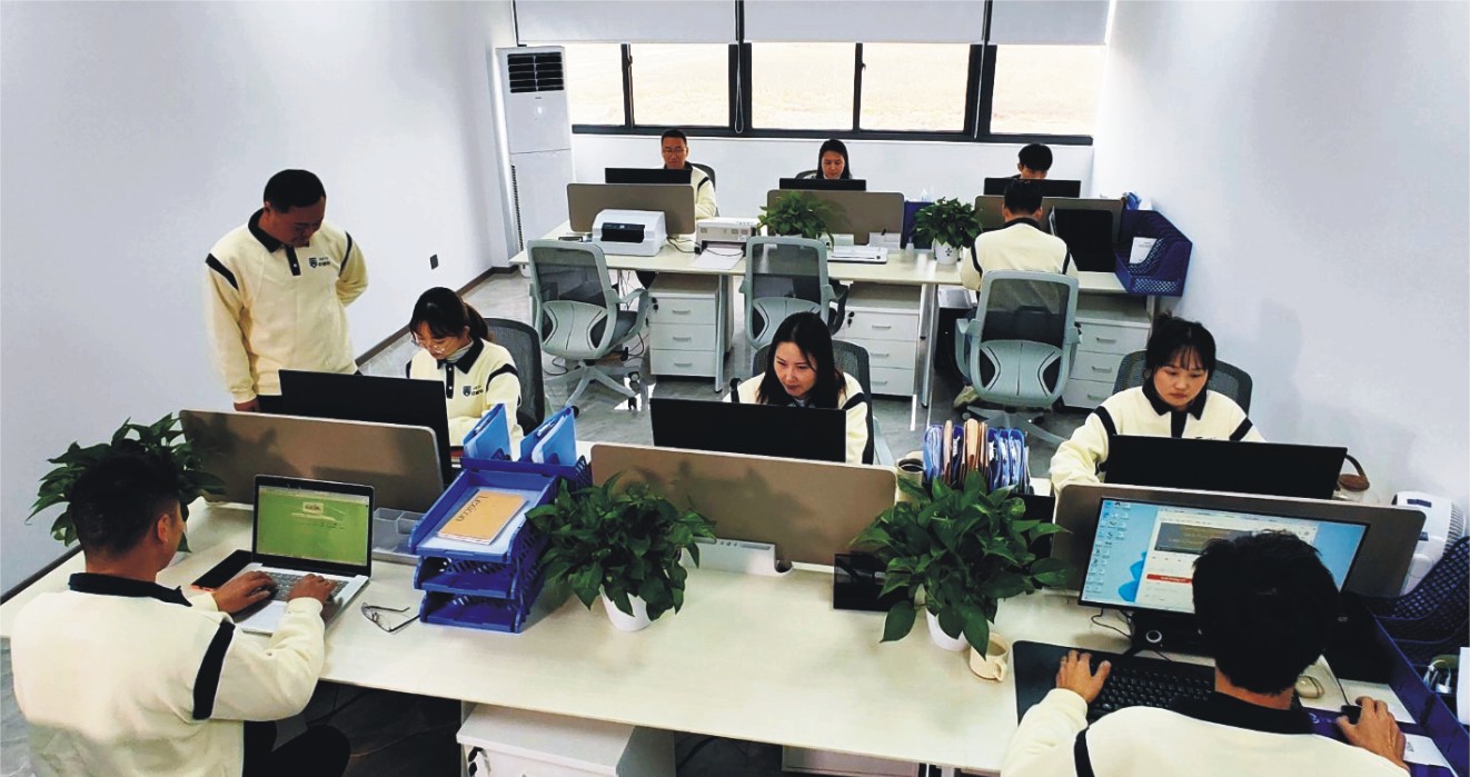
Our skilled technical team offers full support from product selection through after-sales service, helping ensure the best valve performance for your application.