Application Temperature Range Table
| Materials | Medium Temperature (°C) |
|---|
| RPP (Reinforced Polypropylene) | -14°C ~ +90°C |
| UPVC (Unplasticized Polyvinyl Chloride) | -10°C ~ +70°C |
| PVDF (Polyvinylidene Fluoride) | -40°C ~ +140°C |
| CPVC (Chlorinated Polyvinyl Chloride) | -40°C ~ +95°C |
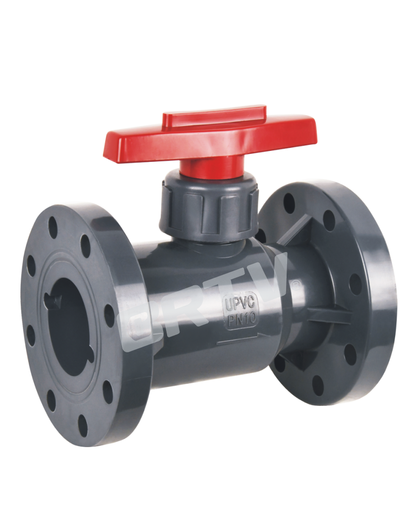
Features
• Quick opening and closing, short operation time; high flow capacity and low flow resistance.
• Compact structure and light weight.
• No metal accessories, PTFE sealing, flange connection, wide applicability.
• Optional flange ball valve with lock (fully open or fully closed).
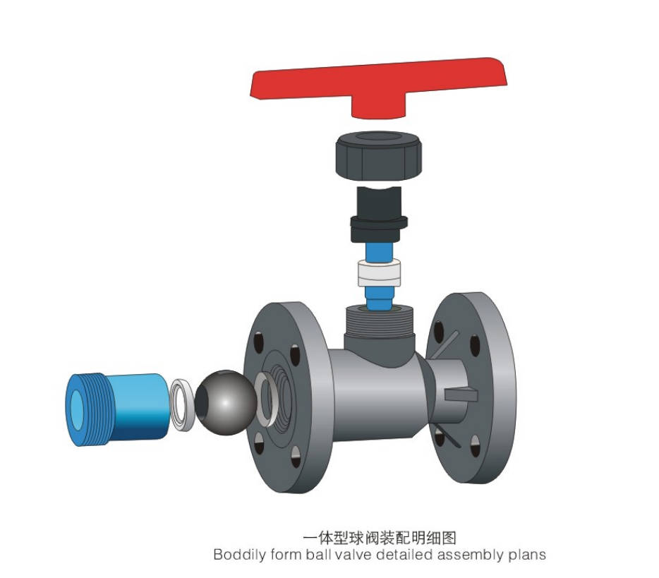
Parts & Material
| No. | Parts | Materials |
|---|
| 1 | Body | FRPP, PPH, UPVC, CPVC, PVDF |
| 2 | Ball Seal | PTFE |
| 3 | Ball | FRPP, PPH, UPVC, CPVC, PVDF |
| 4 | Inner Plug | FRPP, PPH, UPVC, CPVC, PVDF |
| 5 | Stem Seal | PTFE |
| 6 | Locator | FRPP, PPH, UPVC, CPVC, PVDF |
| 7 | Compression Nut | FRPP, PPH, UPVC, CPVC, PVDF |
| 8 | Stem | FRPP, PPH, UPVC, CPVC, PVDF |
| 9 | Handle | ABS |
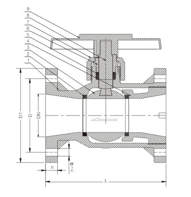
Dimensions Table
| DN | D1 (mm) | D (DIN) | D (JIS) | D (ANSI) | L (mm) | H (mm) | n (HG/DIN) | n (JIS) | n (ANSI) | Φ (HG/DIN) | Φ (JIS) | Φ (ANSI) | Working Pressure (FRPP/PPH) | Working Pressure (UPVC/CPVC) | Working Pressure (PVDF) |
|---|
| 15 | 95 | 65 | 70 | 60 | 100 | 15 | 4 | 4 | 4 | 14 | 15 | 16 | 1.0 | 1.6 | 1.6 |
| 20 | 105 | 75 | 75 | 70 | 120 | 17 | 4 | 4 | 4 | 14 | 15 | 16 | 1.0 | 1.6 | 1.6 |
| 25 | 115 | 85 | 90 | 79 | 140 | 17 | A | 4 | 4 | 14 | 15 | 16 | 1.0 | 1.6 | 1.6 |
| 32 | 135 | 100 | 100 | 89 | 160 | 18 | 4 | 4 | 4 | 18 | 19 | 16 | 1.0 | 1.6 | 1.6 |
| 40 | 145 | 110 | 105 | 98 | 165 | 18 | 4 | 4 | 4 | 18 | 19 | 16 | 1.0 | 1.0 | 1.6 |
| 50 | 160 | 125 | 120 | 121 | 180 | 20 | 4 | 4 | 4 | 18 | 19 | 19 | 1.0 | 1.0 | 1.6 |
| 65 | 180 | 145 | 140 | 140 | 220 | 22 | 4 | 4 | 4 | 18 | 19 | 19 | 1.0 | 1.0 | 1.0 |
| 80 | 195 | 160 | 150 | 152 | 250 | 25 | 8 | 8 | 4* | 18 | 19 | 19 | 1.0 | 1.0 | 1.0 |
| 100 | 215 | 180 | 175 | 190 | 280 | 25 | 8 | 8 | 8 | 18 | 19 | 19 | 1.0 | 1.0 | 1.0 |
| 125 | 245 | 210 | 210 | 216 | 325 | 28 | 8 | 8 | 8 | 18 | 19 | 22 | 0.6 | 0.6 | 1.0 |
| 150 | 280 | 240 | 240 | 241 | 365 | 30 | 8 | 8 | 8 | 22 | 23 | 22 | 0.6 | 0.6 | 1.0 |
| 200 | 335 | 295 | 290 | 298 | 405 | 35 | 8 | 12* | 8 | 22 | 23 | 22 | 0.3 | 0.3 | 0.6 |
| 250 | 400 | 350 | 355 | 362 | 500 | 38 | 12 | 12 | 12 | 22 | 25 | 26 | 0.3 | 0.3 | 0.4 |
| 300 | 455 | 400 | 400 | 432 | 600 | 40 | 12 | 16* | 12 | 22 | 25 | 26 | 0.3 | 0.3 | 0.3 |
Advantage
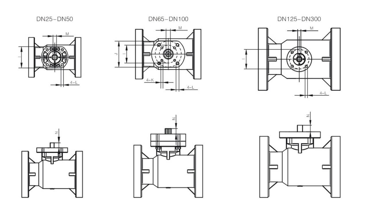
• The original platform ball valve design combines the advantages of flanged ball valves and is compatible with various types of actuators.
• Integrated platform with all-plastic design; actuator installation does not require brackets or connecting sleeves. Optional all-plastic brackets and connecting sleeves are also available to allow smaller pneumatic or electric actuators to be directly mounted on the valve.
• Four-hole positioning with bolt and nut connection provides significantly better strength and stability compared to two-hole positioning or self-tapping screw fixing.
• The PVDF valve stem offers excellent mechanical strength, even under harsh working conditions.
Ball Valve Torque Reference Table
| Size (DN) | Safety Torque | Size (DN) | Safety Torque |
|---|
| 15 | ≤10 | 80 | 45 |
| 20 | ≤10 | 100 | 65 |
| 25 | ≤10 | 125 | 85 |
| 32 | 12 | 150 | 130 |
| 40 | 15 | 200 | 250 |
| 50 | 20 | 250 | 400 |
| 65 | 40 | 300 | 800 |
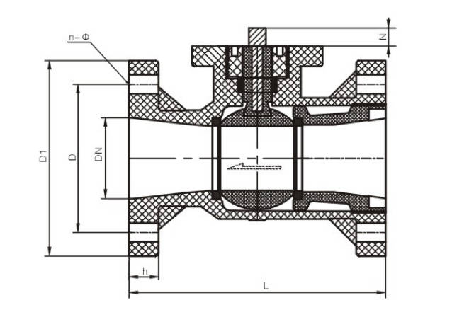
Dimension Table
| DN | D1 | D (DIN) | D (JIS) | D (ANSI) | L | b | n (DIN) | n (JIS) | n (ANSI) | Φ (DIN) | Φ (JIS) | Φ (ANSI) | Working Pressure FRPP/PPH | UPVC/CPVC | PVDF | I | J | M | N |
|---|
| 15 | 95 | 65 | 70 | 60 | 100 | 15 | 4 | 4 | 4 | 14 | 15 | 16 | 1.0 | 1.6 | 1.6 | 70 | / | 11 | 11 |
| 20 | 105 | 75 | 75 | 70 | 120 | 17 | 4 | 4 | 4 | 14 | 15 | 16 | 1.0 | 1.6 | 1.6 | 70 | / | 11 | 11 |
| 25 | 115 | 85 | 90 | 79 | 140 | 17 | 4 | 4 | 4 | 14 | 15 | 16 | 1.0 | 1.6 | 1.6 | 70 | / | 11/14* | 11 |
| 32 | 135 | 100 | 100 | 89 | 160 | 18 | 4 | 4 | 4 | 18 | 19 | 16 | 1.0 | 1.6 | 1.6 | 70 | / | 11/14* | 11 |
| 40 | 145 | 110 | 105 | 98 | 165 | 18 | 4 | 4 | 4 | 18 | 19 | 16 | 1.0 | 1.0 | 1.6 | 70 | / | 14/17* | 17 |
| 50 | 160 | 125 | 120 | 121 | 180 | 20 | 4 | 4 | 4 | 18 | 19 | 19 | 1.0 | 1.0 | 1.6 | 70 | / | 14/17* | 17 |
| 65 | 180 | 145 | 140 | 140 | 220 | 22 | 4 | 4 | 4 | 18 | 19 | 19 | 1.0 | 1.0 | 1.0 | 70 | 102 | 14/17 | 21 |
| 80 | 195 | 160 | 150 | 152 | 250 | 25 | 8 | 8 | 4* | 18 | 19 | 19 | 1.0 | 1.0 | 1.0 | 70 | 102 | 14/17 | 21 |
| 100 | 215 | 180 | 175 | 190 | 280 | 25 | 8 | 8 | 8 | 18 | 19 | 19 | 1.0 | 1.0 | 1.0 | 70 | 102 | 17/22 | 24 |
| 125 | 245 | 210 | 210 | 216 | 325 | 30 | 8 | 8 | 8 | 18 | 19 | 22 | 0.6 | 0.6 | 0.6 | 125 | / | 22/27* | — |
| 150 | 280 | 240 | 240 | 241 | 365 | 30 | 8 | 8 | 8 | 22 | 23 | 22 | 0.6 | 0.6 | 0.6 | 125 | / | 22/27* | — |
| 200 | 335 | 295 | 290 | 298 | 405 | 35 | 8 | 12* | 8 | 22 | 23 | 22 | 0.3 | 0.3 | 0.3 | 125 | / | 22/27* | — |
| 250 | 400 | 350 | 355 | 362 | 500 | 38 | 12 | 12 | 12 | 22 | 25 | 26 | 0.3 | 0.3 | 0.3 | 125 | / | 22/27* | — |
| 300 | 455 | 400 | 400 | 432 | 600 | 40 | 12 | 16* | 12 | 22 | 25 | 26 | 0.3 | 0.3 | 0.3 | — | — | — | — |
Manufacturing Process
Step 1: Order and Design
Based on customer requirements (pressure rating, dimensions, connection standards, etc.), we perform structural design and drawing confirmation for flanged ball valves, including flange standards (ANSI/DIN/JIS) and sealing solutions.
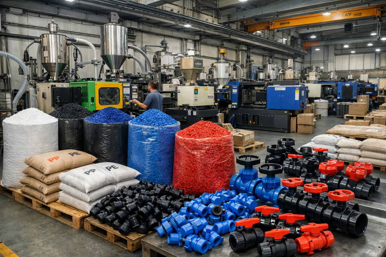
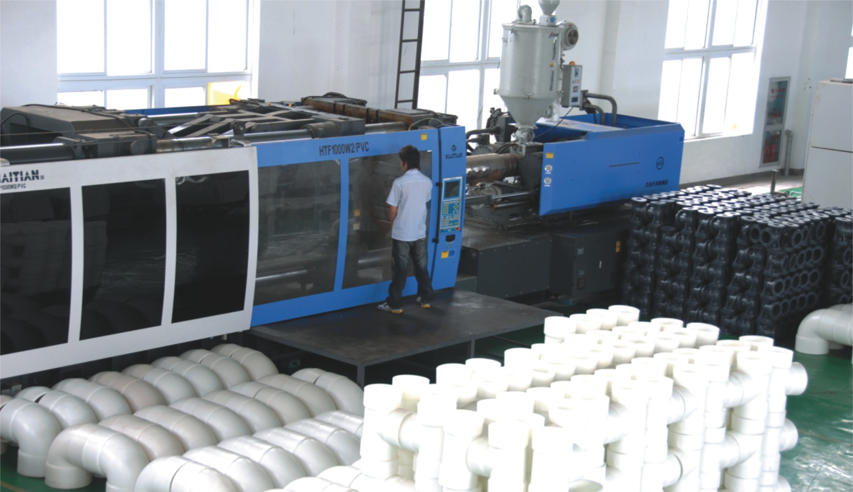
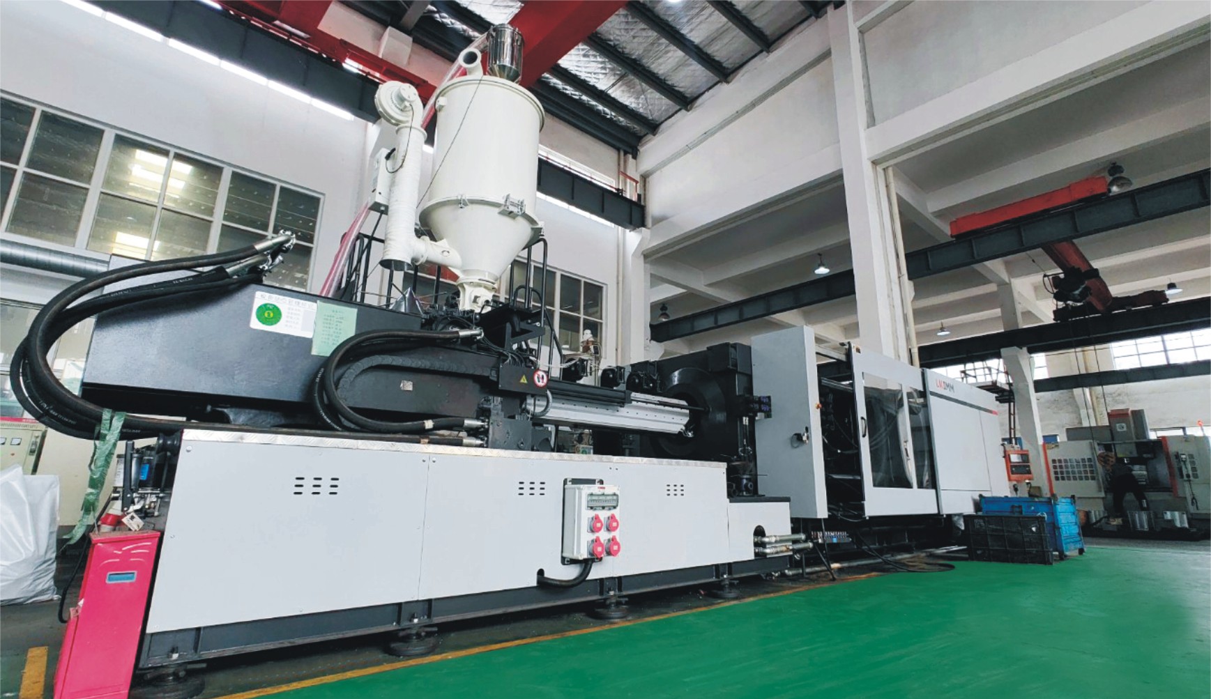
Step 2: Raw Material Preparation & Molding
Select raw materials such as UPVC, CPVC, or PP, and use injection molding or compression molding processes to form key components of the flanged ball valve, including the valve body, ball, and end caps.
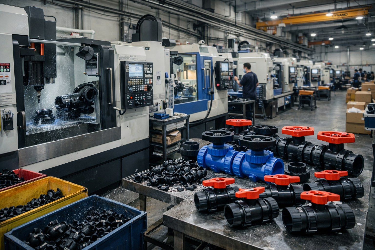
Step 3: Machining
Perform precision machining on the molded components, including sealing surface machining, drilling of flange holes, and dimensional finishing, to ensure the flanged ball valve’s sealing performance and assembly accuracy.
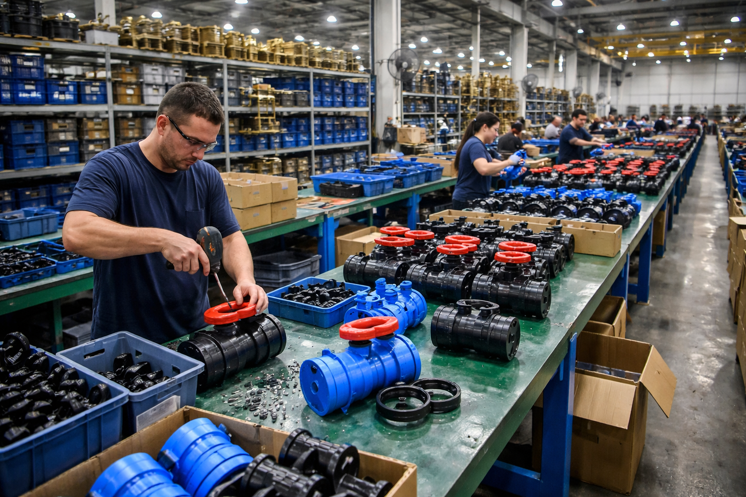
Step 4: Assembly
Assemble components such as the ball, seat, seal ring, and stem to complete the overall assembly of the flanged ball valve, followed by preliminary functional testing.
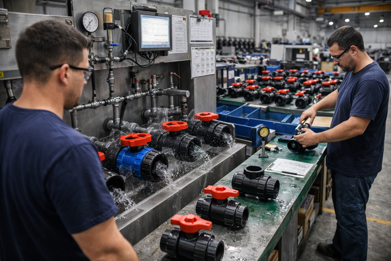
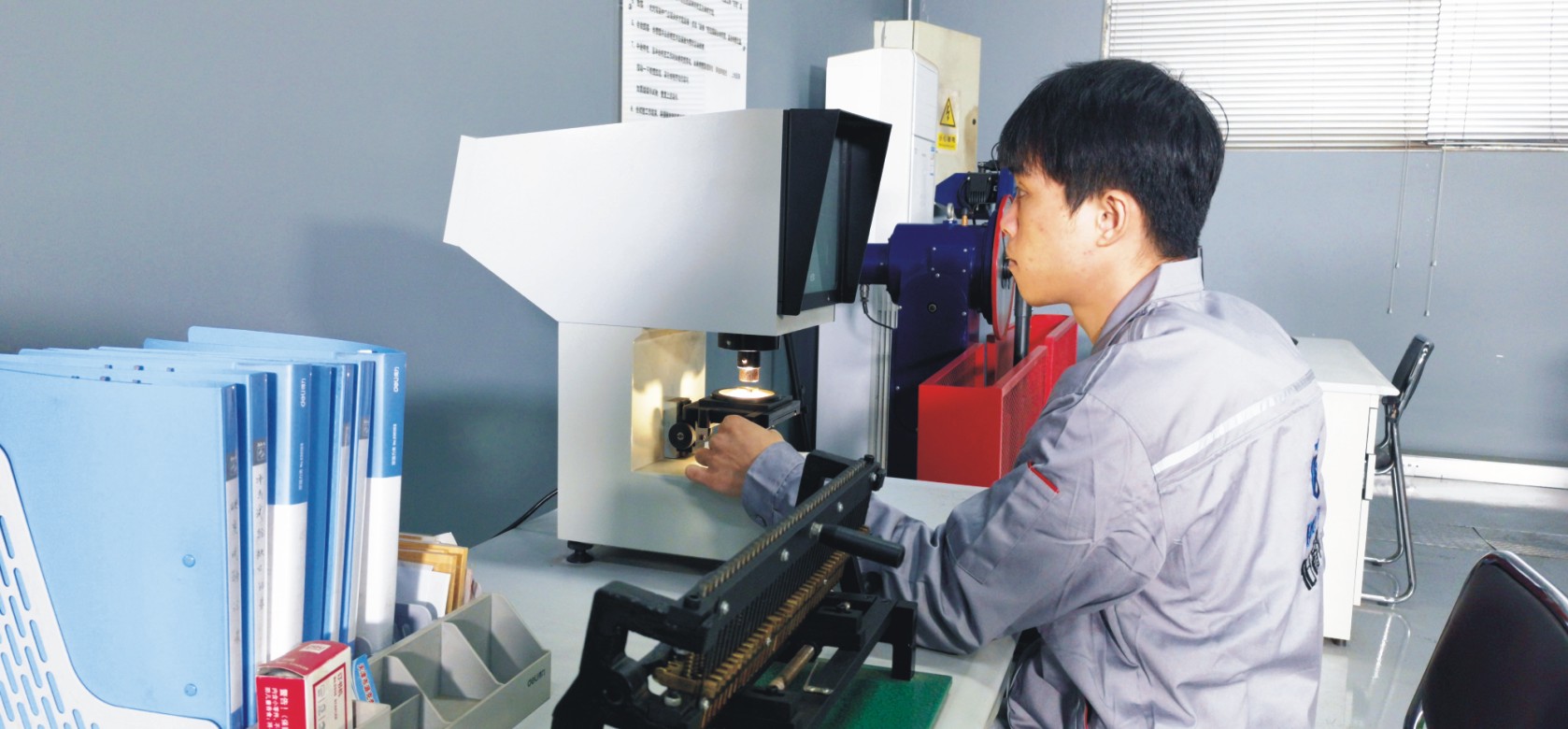
Step 5: Testing & Quality Assurance
Conduct pressure testing, seal testing, and opening/closing torque testing on the flanged ball valve to ensure the product meets relevant standards and quality requirements.
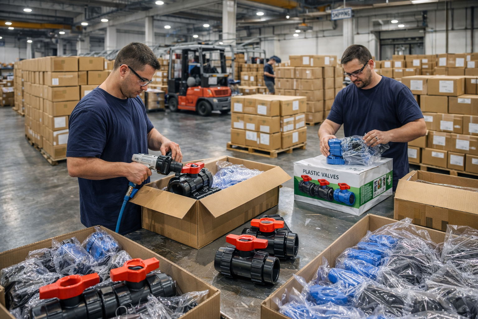
Step 6: Finishing, Packaging and Shipment
Complete cleaning, protective treatment, and labeling; package the product and arrange for shipment to ensure it remains undamaged during transit.
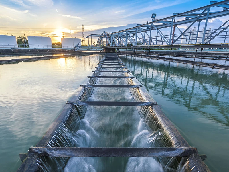
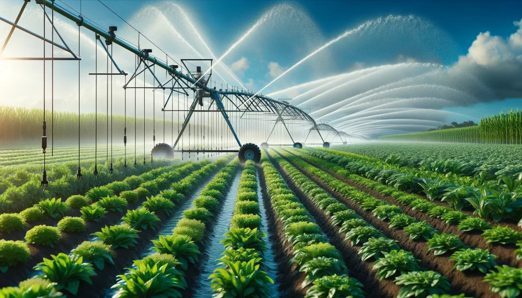
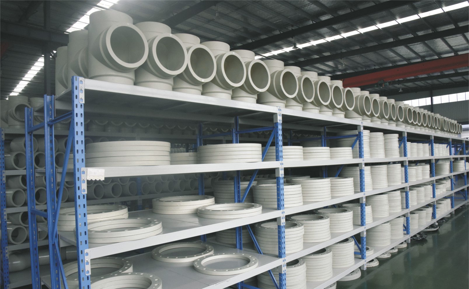
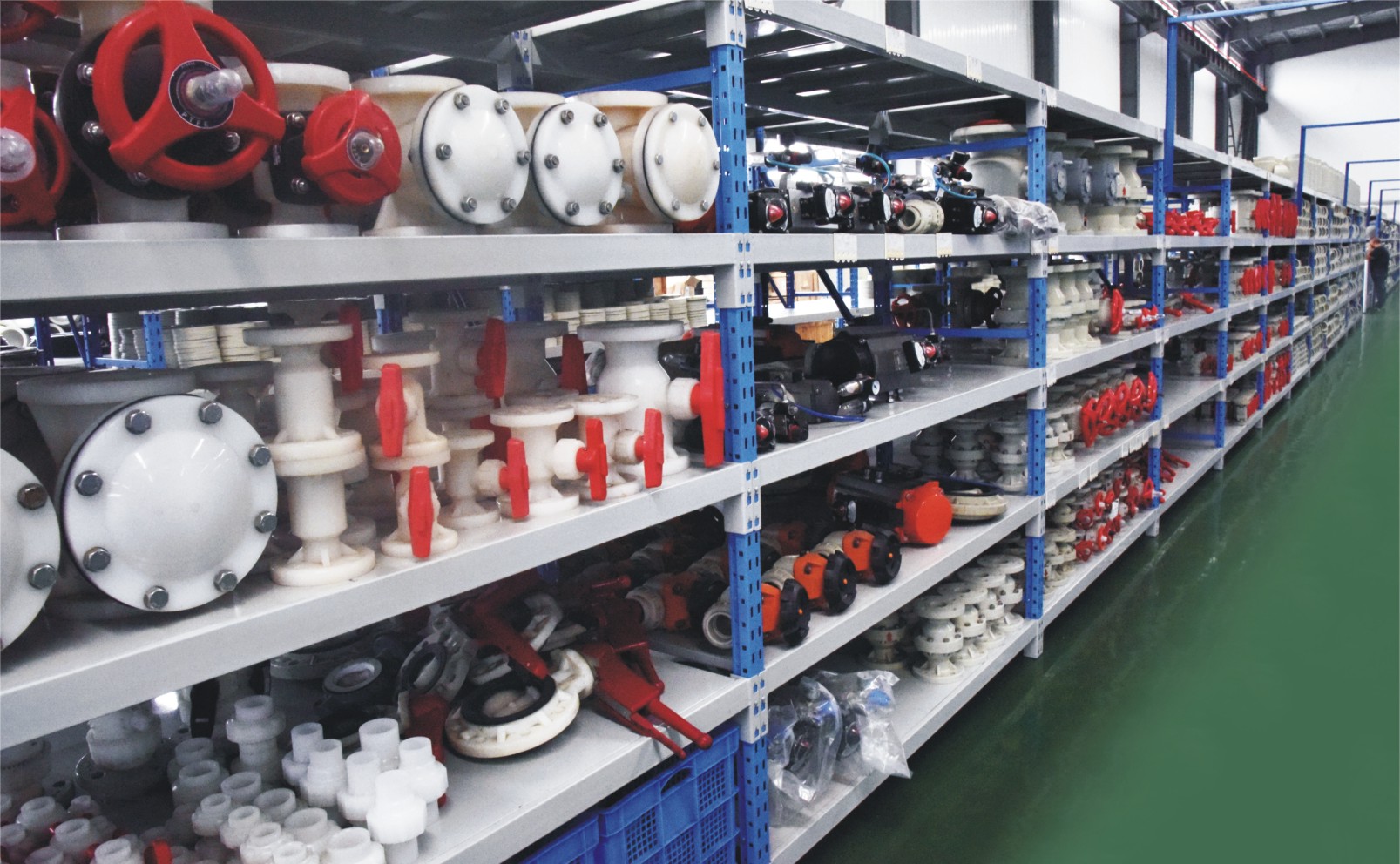
Applications
Piping systems for corrosive media widely used in industrial sectors such as chemicals, environmental protection, water treatment, food, and pharmaceuticals
These valves are widely used in:
Agriculture and Irrigation
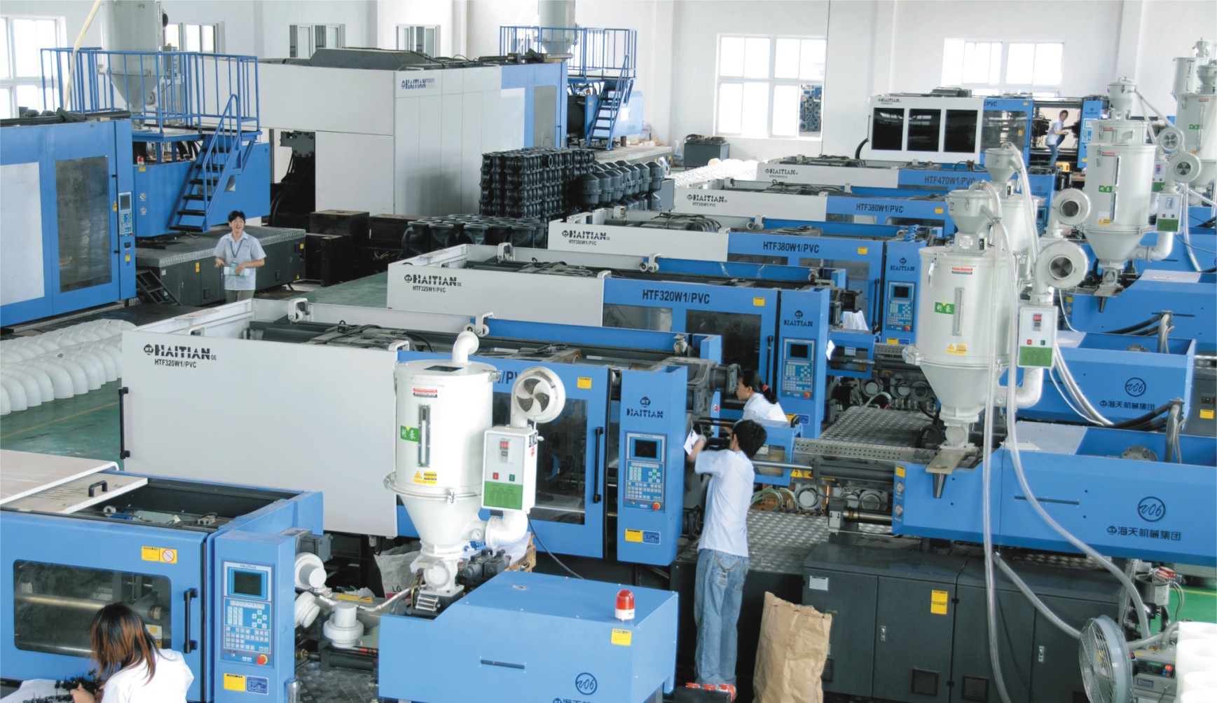
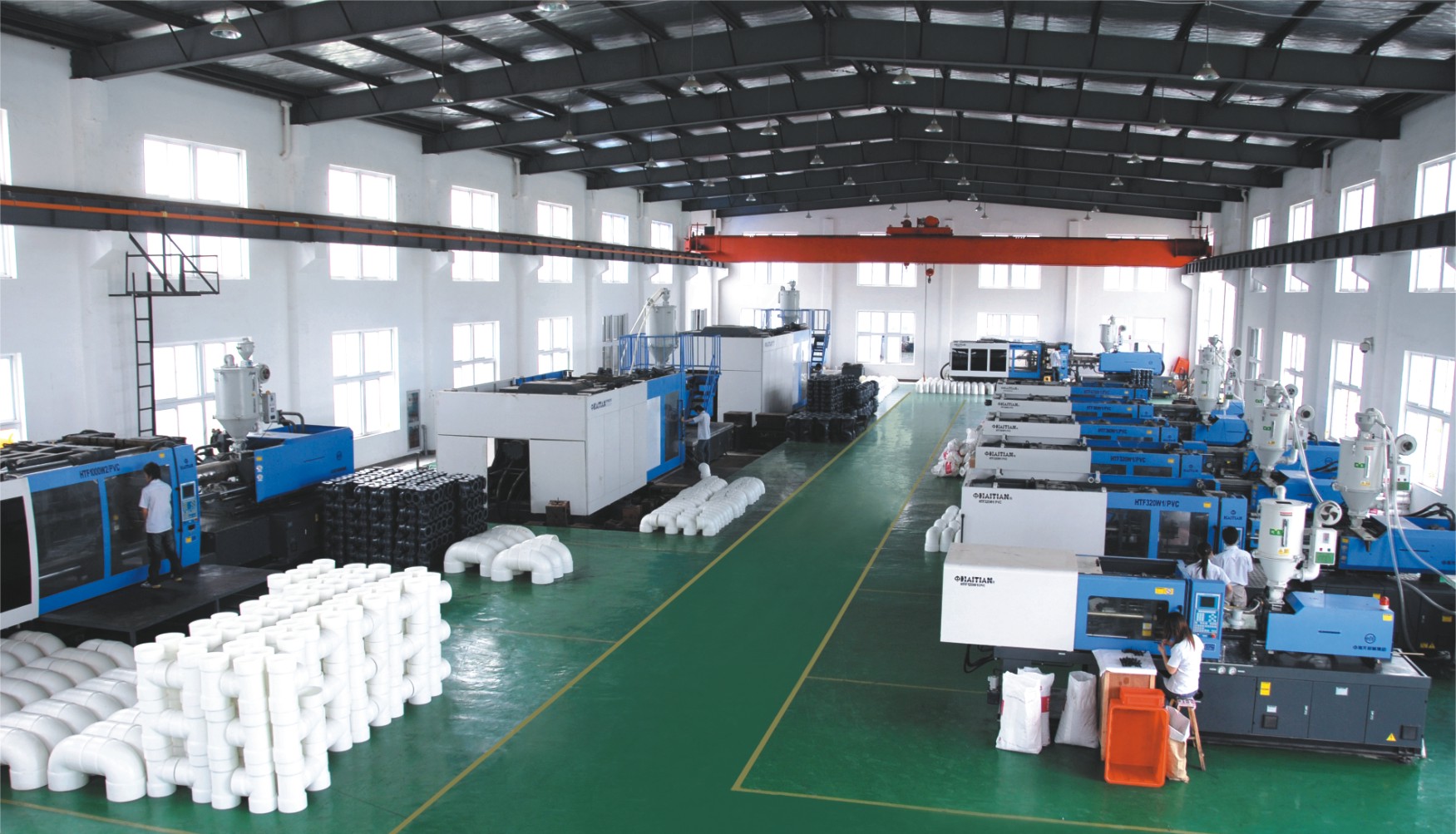
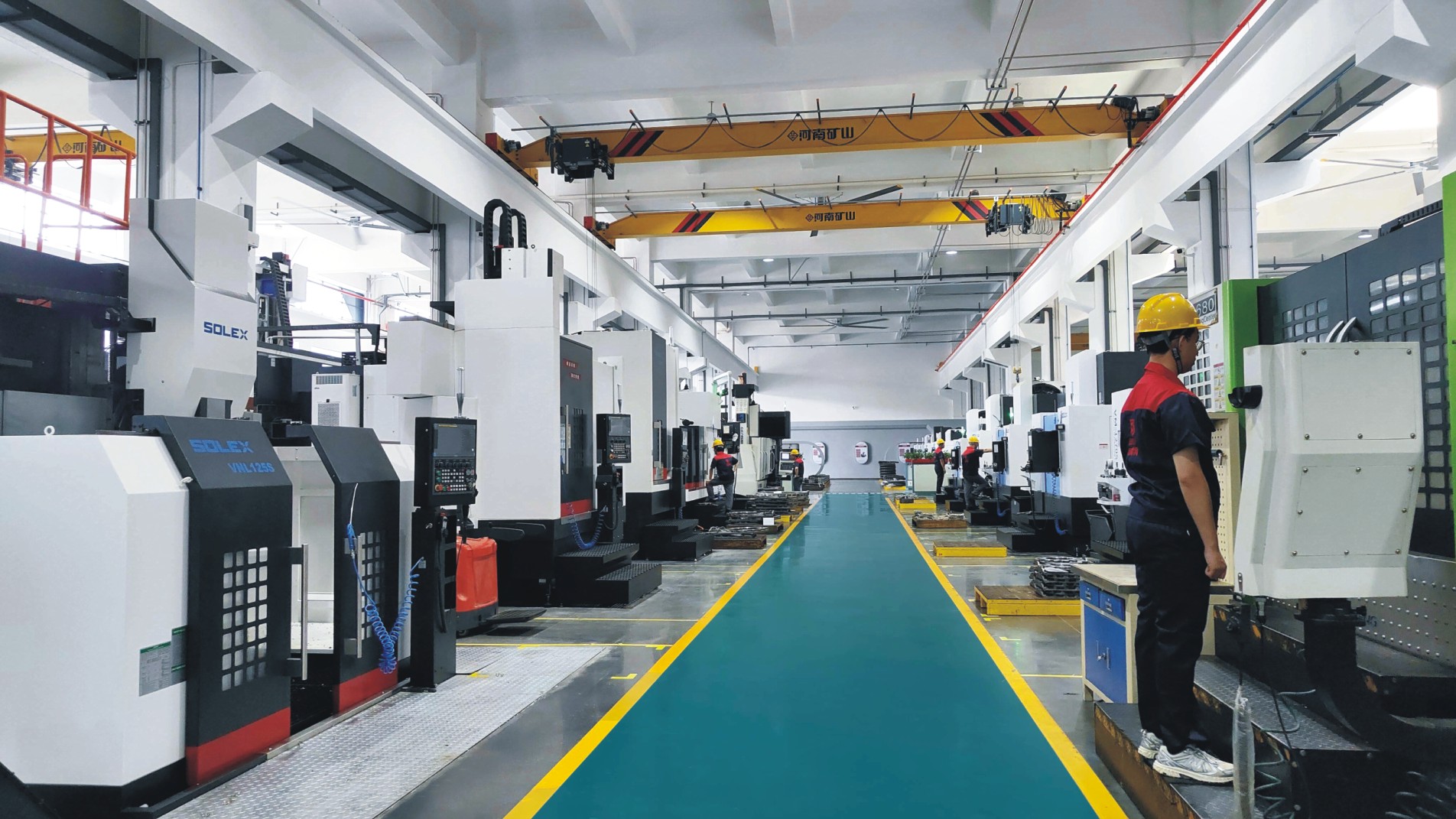
Factory Environment
Why Choose Us
Superior Quality
Our valves are produced from high-grade materials and subjected to strict quality inspections to guarantee dependable performance in challenging industrial environments.
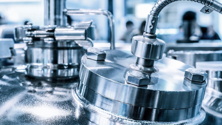
Advanced Technology
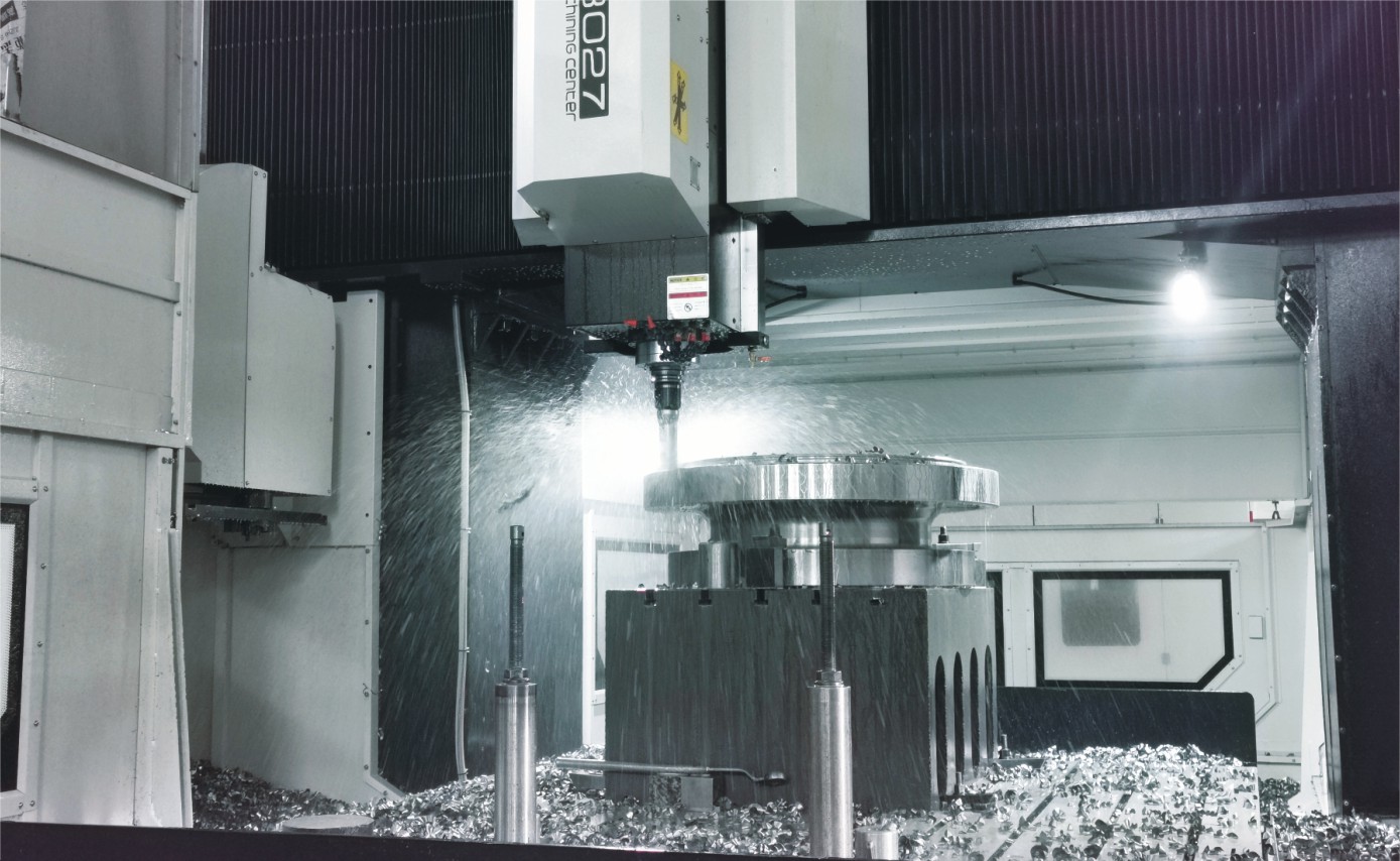
With cutting-edge CNC machining systems and high-precision manufacturing equipment, we ensure valves are made with outstanding accuracy and uniformity.
Competitive Pricing
By streamlining production processes and sourcing materials in bulk, we provide premium-quality valves at competitive prices while maintaining excellent standards.
Expert Support
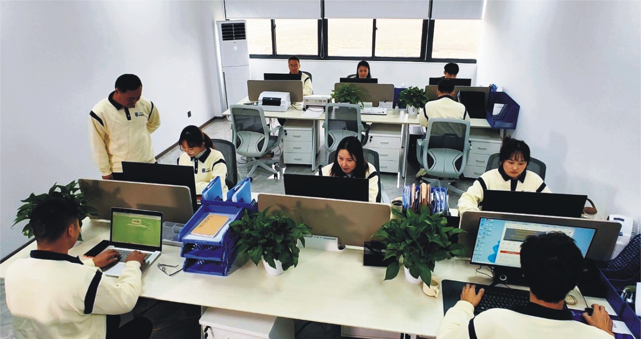
Our skilled technical team offers full support from product selection through after-sales service, helping ensure the best valve performance for your application.