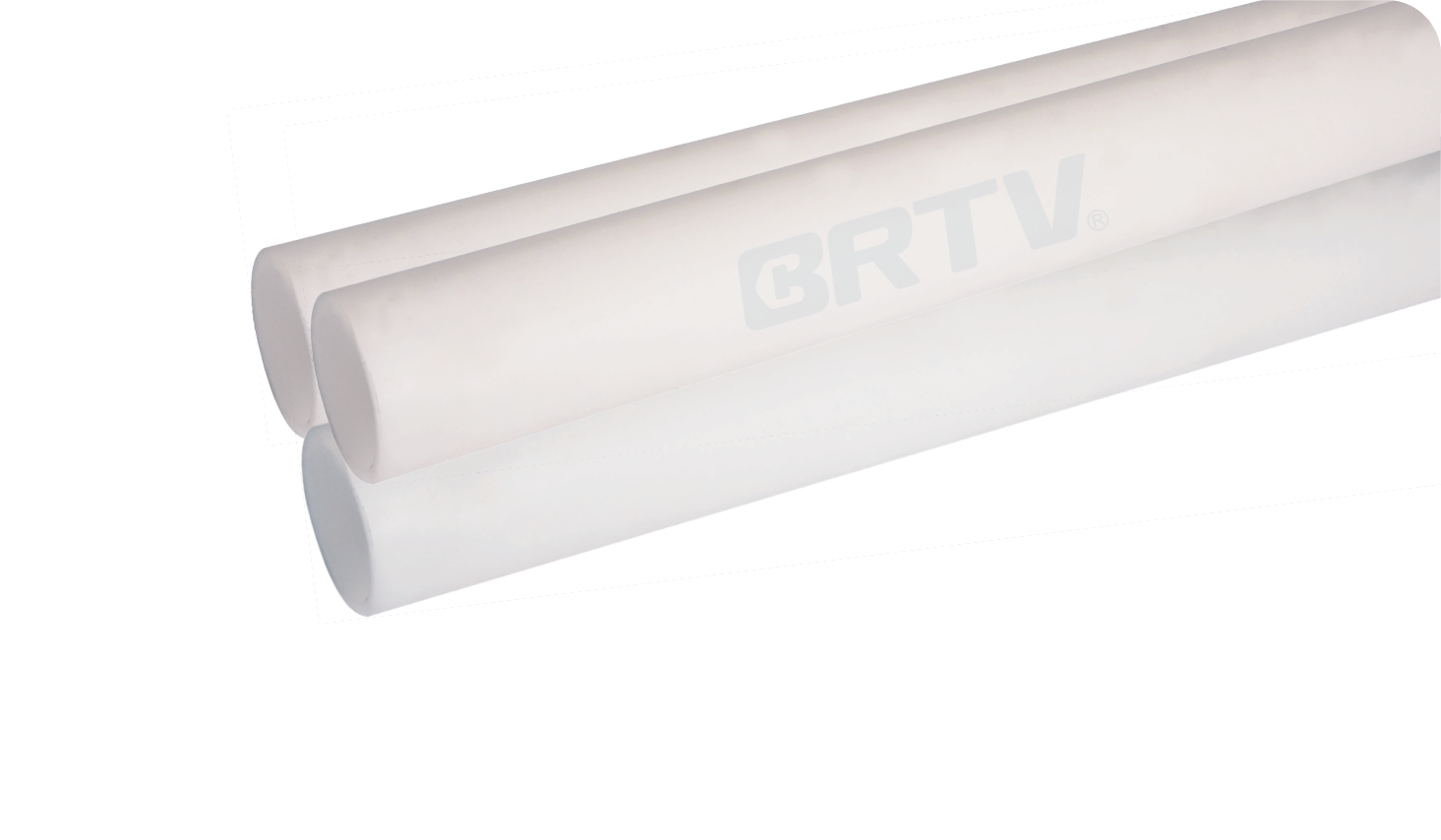
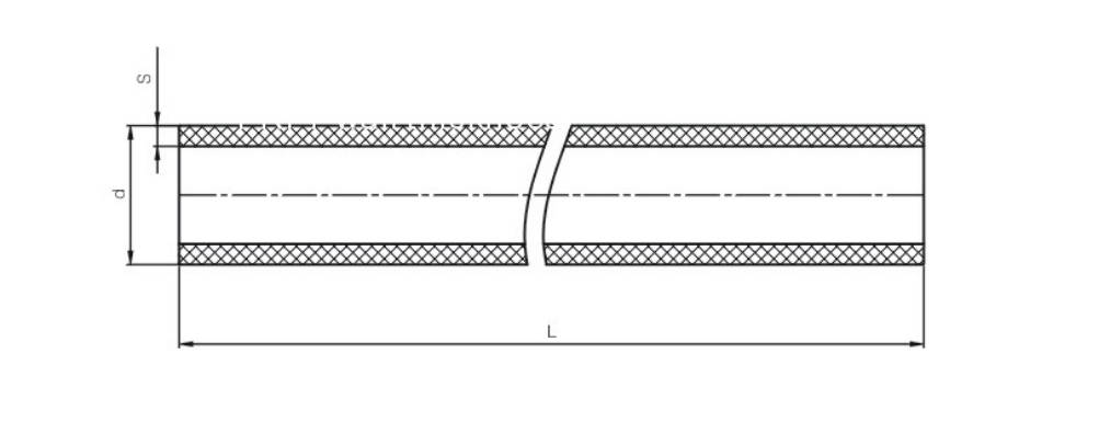
FRPP Pipe Dimension Table
| DN (mm) | Outer Diameter (mm) | FRPP Thickness (0.4 MPa) | FRPP Thickness (0.6 MPa) | FRPP Thickness (1.0 MPa) | PPH Thickness (0.6 MPa / S3.3) | PPH Thickness (1.0 MPa / S5) | Fiberglass Layer (mm) |
|---|
| 15 | 20 | — | — | 2.0 | — | 2.0 | 3 |
| 20 | 25 | — | — | 2.1 | — | 2.3 | 3 |
| 25 | 32 | — | — | 2.7 | — | 2.9 | 3 |
| 32 | 40 | — | — | 3.4 | — | 3.7 | 3 |
| 40 | 50 | — | — | 4.2 | — | 4.6 | 3 |
| 50 | 65 | — | — | 5.2 | — | 5.8 | 3 |
| 65 | 80 | — | — | 6.2 | — | 6.8 | 3 |
| 80 | 90 | — | — | 7.5 | — | 8.2 | 3 |
| 100 | 110 | — | 5.7 | 9.1 | — | 10.0 | 3 |
| 125 | 140 | — | 7.2 | 11.6 | — | 12.7 | 3 |
| 150 | 160 | — | 8.3 | 13.3 | — | 14.6 | 3 |
| 200 | 225 | 7.9 | 11.6 | 18.7 | 12.8 | 20.5 | 3 |
| 250 | 280 | 9.9 | 14.4 | — | 15.9 | 25.4 | 4 |
| 300 | 315 | 11.1 | 16.2 | — | 17.9 | 28.6 | 4 |
| 350 | 355 | 12.5 | 18.3 | — | 20.1 | 32.2 | 4 |
| 400 | 400 | 14.1 | 20.6 | — | 22.7 | 36.3 | 5 |
Note: FRPP and PPH are generally supplied in lengths of 5 meters per piece.
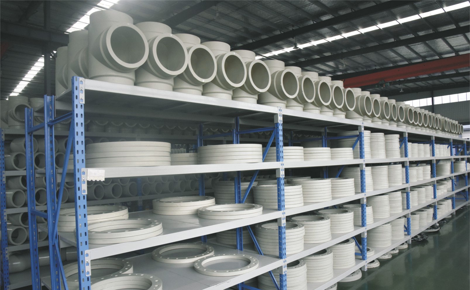
FRPP List of Hot-melt Welded Fittings
| DN | 90° Elbow | Coupling | Tee | 45° Elbow | Flange | Lined Steel Flange | End Cap | Union | Cross | Male Coupling | Y Tee |
|---|
| DN15 | ○ | ○ | ○ | ○ | ○ | — | ○ | ○ | — | — | — |
| DN20 | ○ | ○ | ○ | ○ | ○ | — | ○ | ○ | — | — | — |
| DN25 | ○ | ○ | ○ | ○ | ○ | ○ | ○ | ○ | — | ○ | — |
| DN32 | ○ | ○ | ○ | ○ | ○ | ○ | ○ | ○ | — | ○ | — |
| DN40 | ○ | ○ | ○ | ○ | ○ | ○ | ○ | ○ | — | ○ | — |
| DN50 | ○ | ○ | ○ | ○ | ○ | ○ | ○ | ○ | ○ | ○ | ○ |
| DN65 | ○ | ○ | ○ | ○ | ○ | ○ | ○ | ○ | ○ | ○ | — |
| DN80 | ○ | ○ | ○ | ○ | ○ | ○ | ○ | ○ | ○ | ○ | — |
| DN100 | ○ | ○ | ○ | ○ | ○ | ○ | ○ | ○ | ○ | ○ | — |
FRPP List of Butt Welded Fittings
| DN | 90° Elbow | Tee | 45° Elbow | Flange | Lined Steel Flange |
|---|
| DN50 | ○ | ○ | — | ○ | — |
| DN65 | ○ | ○ | — | ○ | — |
| DN80 | ○ | ○ | — | ○ | — |
| DN100 | ○ | ○ | — | ○ | — |
| DN125 | ○ | ○ | ○ | ○ | ○ |
| DN150 | ○ | ○ | ○ | ○ | ○ |
| DN200 | ○ | ○ | ○ | ○ | ○ |
| DN250 | ○ | ○ | ○ | ○ | ○ |
| DN300 | ○ | ○ | ○ | ○ | ○ |
FRPP List of Socket Welded Fittings
| DN | 90° Elbow | Coupling | Tee | 45° Elbow | Flange | Blind Flange |
|---|
| DN15 | ○ | ○ | ○ | ○ | ○ | ○ |
| DN20 | ○ | ○ | ○ | ○ | ○ | ○ |
| DN25 | ○ | ○ | ○ | ○ | ○ | ○ |
| DN32 | ○ | ○ | ○ | ○ | ○ | ○ |
| DN40 | ○ | ○ | ○ | ○ | ○ | ○ |
| DN50 | ○ | ○ | ○ | ○ | ○ | ○ |
| DN65 | ○ | ○ | ○ | ○ | ○ | ○ |
| DN80 | ○ | ○ | ○ | ○ | ○ | ○ |
| DN100 | ○ | ○ | ○ | ○ | ○ | ○ |
| DN125 | ○ | ○ | ○ | ○ | ○ | ○ |
| DN150 | ○ | ○ | ○ | ○ | ○ | ○ |
| DN200 | ○ | ○ | ○ | ○ | ○ | ○ |
| DN250 | ○ | ○ | ○ | ○ | ○ | ○ |
| DN300 | ○ | ○ | ○ | ○ | ○ | ○ |
| DN350 | ○ | ○ | ○ | ○ | ○ | ○ |
| DN400 | ○ | ○ | ○ | ○ | ○ | ○ |
FRPP List of Threaded Fittings
| DN | 90° Elbow | Coupling | Tee | Flange | Male Coupling | Flange | Union |
|---|
| DN15 | ○ | ○ | ○ | ○ | ○ | ○ | ○ |
| DN20 | ○ | ○ | ○ | ○ | ○ | ○ | ○ |
| DN25 | ○ | ○ | ○ | ○ | ○ | ○ | ○ |
| DN32 | ○ | ○ | ○ | ○ | ○ | ○ | ○ |
| DN40 | ○ | ○ | ○ | ○ | ○ | ○ | ○ |
| DN50 | ○ | ○ | ○ | ○ | ○ | ○ | ○ |
Manufacturing Process
Step 1: Order and Design
Determine the specifications of the FRPP pipe (diameter, pressure rating, length, etc.) based on customer requirements. Finalize the structural design and production drawings to ensure compliance with corrosion resistance and operational conditions.
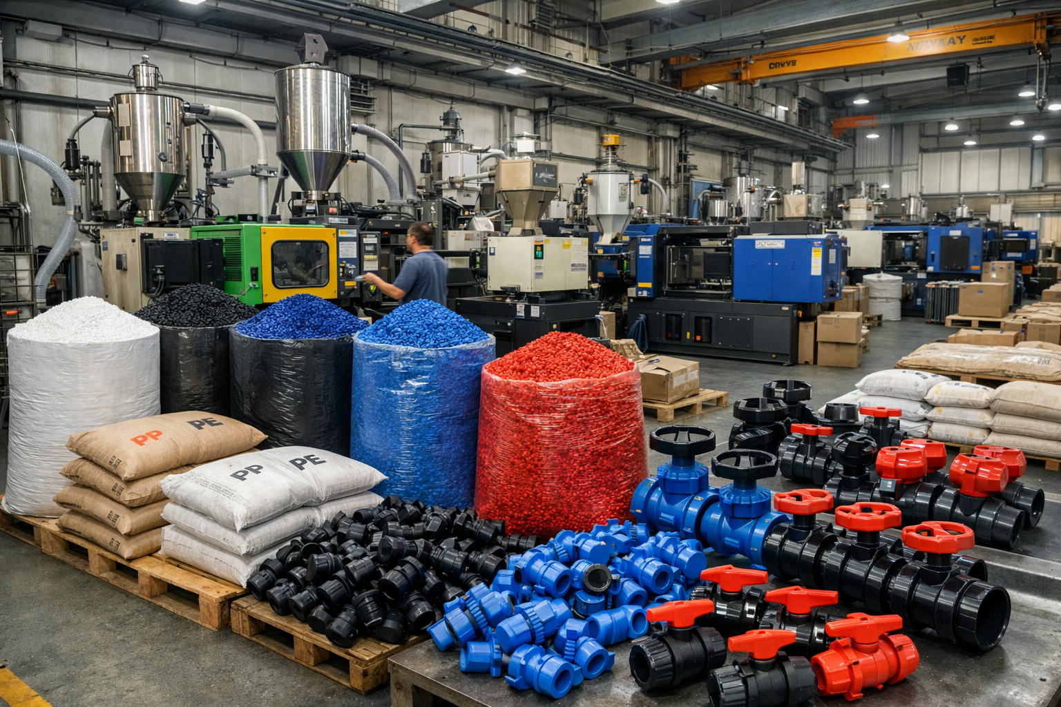
Step 2: Raw Material Preparation & Molding
Select high-quality glass-fiber-reinforced polypropylene (FRPP) raw materials, blend the ingredients, and extrude the FRPP pipe at high temperatures. Control temperature and pressure to ensure uniformity and strength of the pipe.
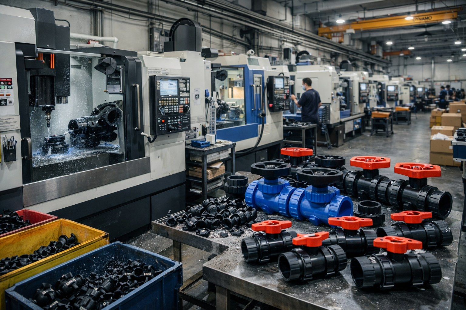
Step 3: Machining
Perform sizing, cutting, and end-face processing (such as chamfering and beveling) on the molded FRPP pipes to ensure dimensional accuracy and connection sealing performance.
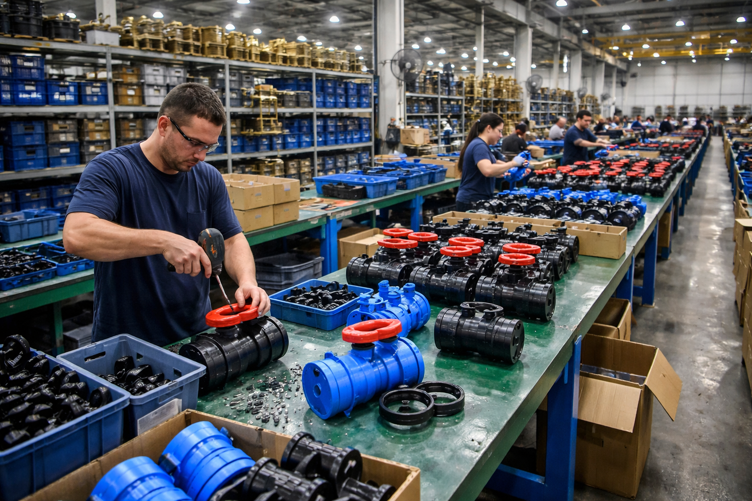
Step 4: Assembly
Assemble the FRPP pipes using appropriate connection methods (flanges, socket joints, or welding) according to project requirements, and complete a system pre-assembly inspection.
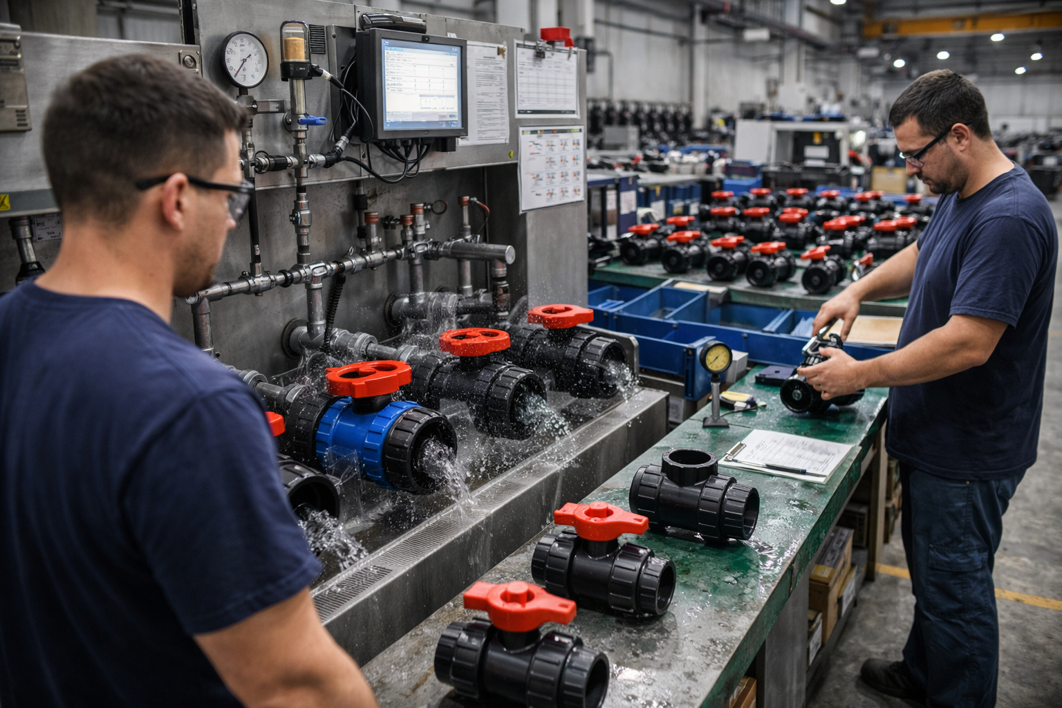
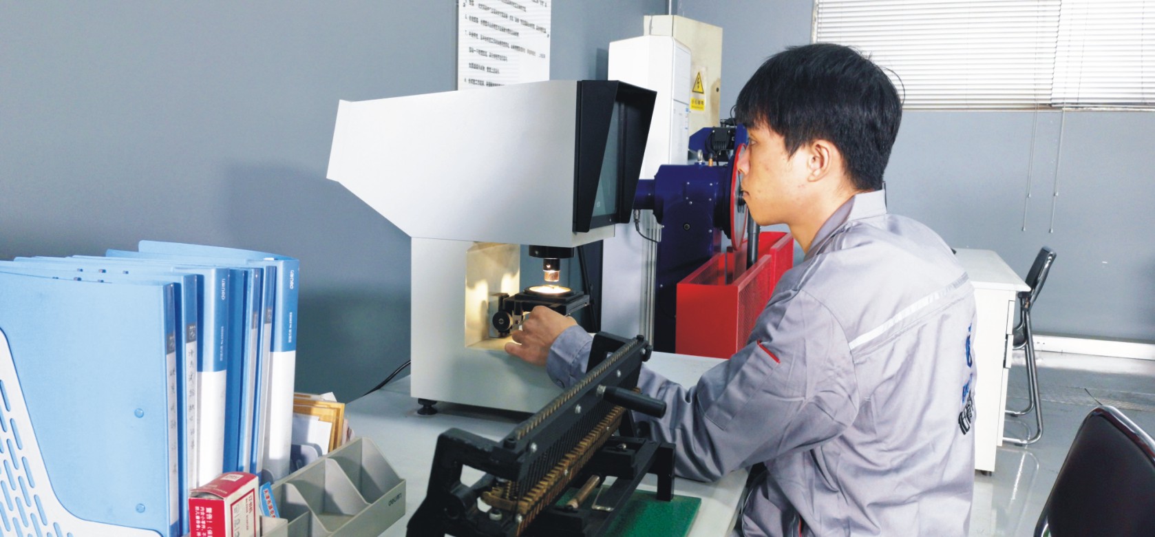
Step 5: Testing & Quality Assurance
The FRPP pipe undergoes visual inspection, dimensional measurement, and pressure testing (such as hydrostatic testing) to ensure the product meets relevant standards and usage requirements.
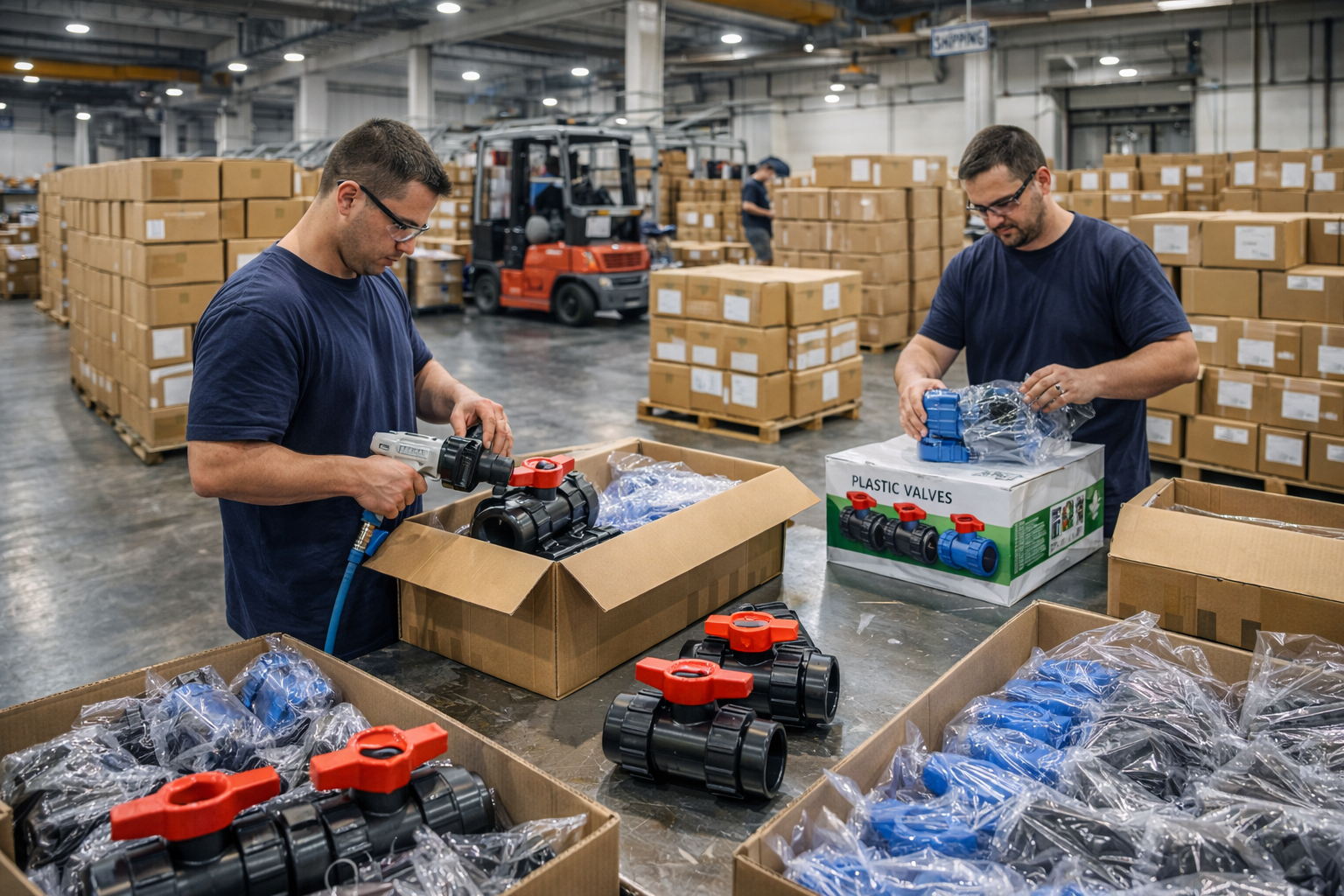
Step 6: Finishing, Packaging and Shipment
After cleaning and protective treatment, the pipe is packaged (dust-proof and impact-resistant) with clear labeling. Transportation and shipment are arranged to ensure safe delivery to the customer.
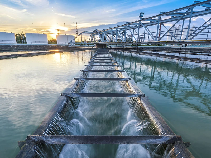
Applications
Widely used in the chemical, smelting, medical, building drainage, petroleum, power, and metallurgical industries
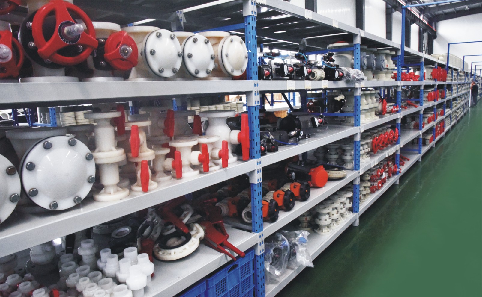
These valves are widely used in:
Agriculture and Irrigation
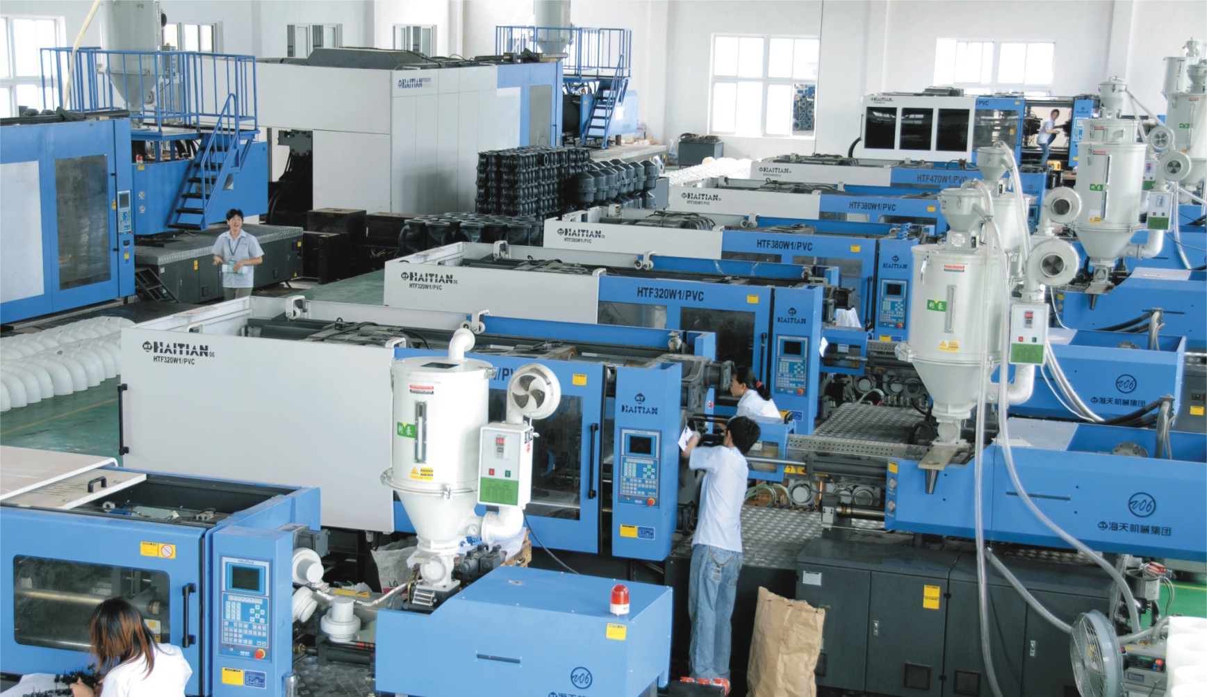
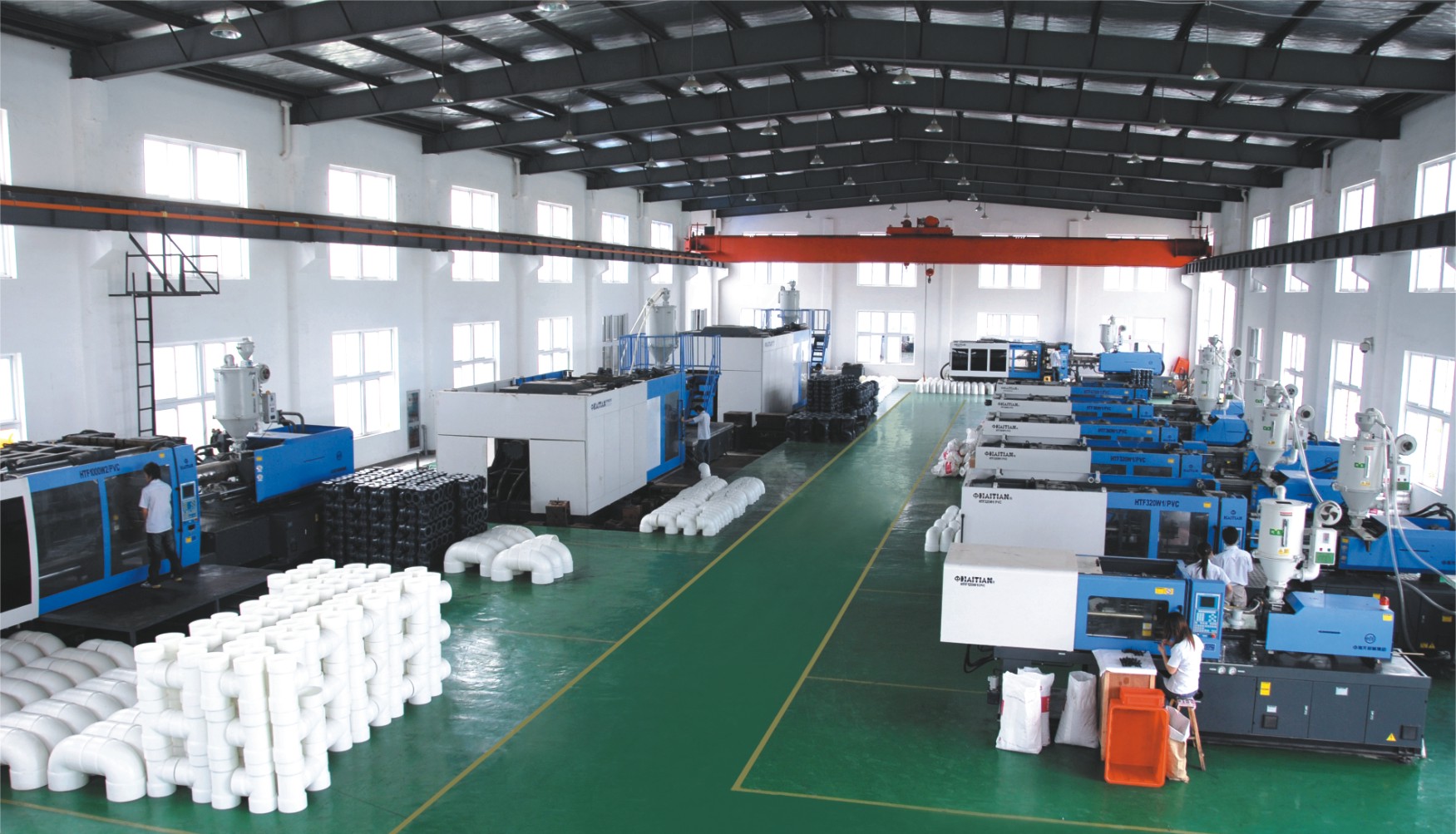
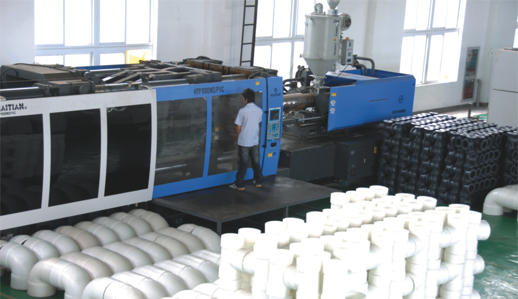
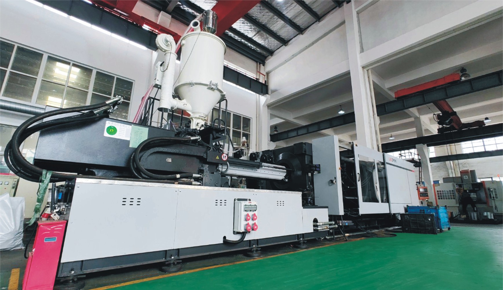
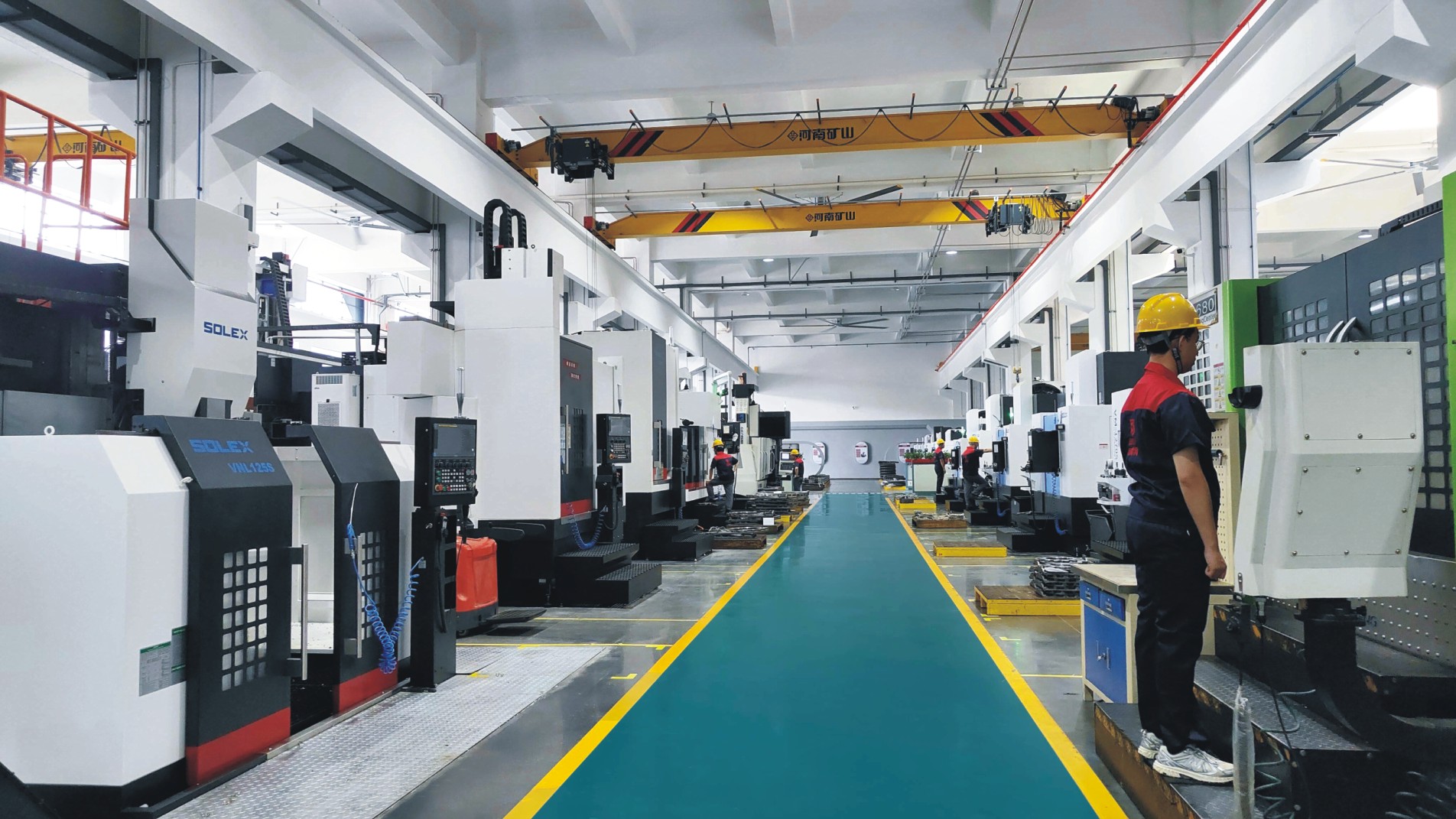
Factory Environment
Why Choose Us
Superior Quality
Our valves are produced from high-grade materials and subjected to strict quality inspections to guarantee dependable performance in challenging industrial environments.
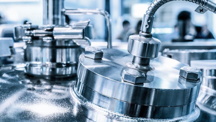
Advanced Technology
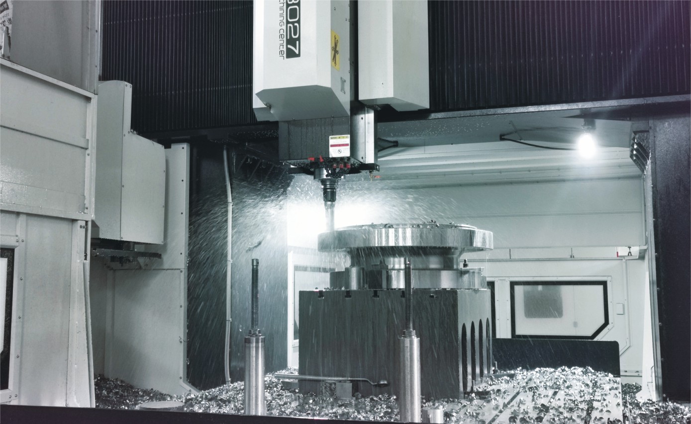
With cutting-edge CNC machining systems and high-precision manufacturing equipment, we ensure valves are made with outstanding accuracy and uniformity.
Competitive Pricing
By streamlining production processes and sourcing materials in bulk, we provide premium-quality valves at competitive prices while maintaining excellent standards.
Expert Support
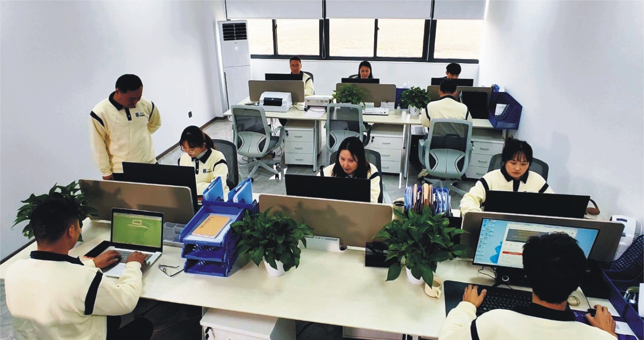
Our skilled technical team offers full support from product selection through after-sales service, helping ensure the best valve performance for your application.