Application Temperature Range Table
| Materials | Medium Temperature (°C) |
|---|
| RPP (Reinforced Polypropylene) | -14°C ~ +90°C |
| UPVC (Unplasticized Polyvinyl Chloride) | -10°C ~ +70°C |
| PVDF (Polyvinylidene Fluoride) | -40°C ~ +140°C |
| CPVC (Chlorinated Polyvinyl Chloride) | -40°C ~ +95°C |
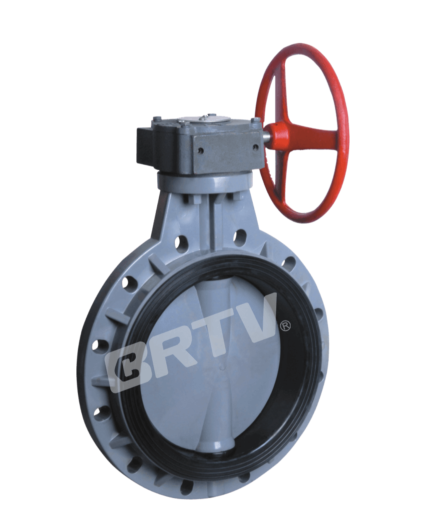
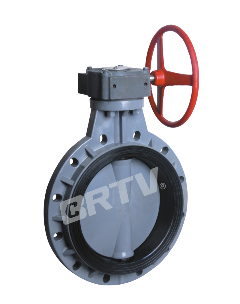
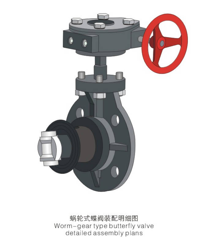
Features
• Sealing performance is improved due to the specially designed seat.
• Thickened valve body with reinforcing ribs and no hollow design; optimized to reduce stress concentration and enhance strength under harsh conditions.
• Spherical disc design provides superior durability and improved Cv value.
• Optional worm gear box materials include cast iron (default), plastic, or aluminum alloy.
Parts & Material
| No. | Parts | Materials |
|---|
| 1 | Gear Box | Cast Iron, Aluminum Alloy, Plastic |
| 2 | Body | FRPP, PPH, UPVC, CPVC, PVDF |
| 3 | Seat | EPDM, FPM |
| 4 | Stem | Steel, Stainless Steel |
| 5 | Disc | FRPP, PPH, UPVC, CPVC, PVDF |
| 6 | Disc O-ring | EPDM, FPM |
| 7 | Stud Bolt & Nut | Steel & Plastic Nuts, Stainless Steel |
| 8 | Stem O-ring | EPDM, FPM |
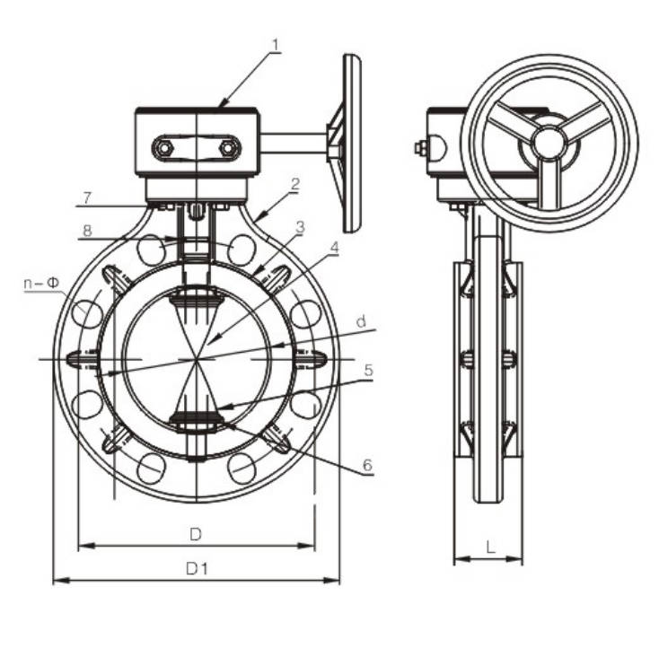
Dimensions Table
| DN | d | D (HG/DIN) | D (JIS) | D (ANSI) | D1 | L | n (HG/DIN) | n (JIS) | n (ANSI) | Working Pressure (MPa) |
|---|
| 125 | 131 | 210 | 210 | 216 | 255 | 62 | 8 | 8 | 8 | 0.6# |
| 150 | 153 | 240 | 240 | 241 | 285 | 67 | 8 | 8 | 8 | 0.6# |
| 200 | 205 | 295 | 290 | 298 | 340 | 85 | 8 | 12* | 8 | 0.6# |
| 250 | 259 | 350 | 355 | 362 | 410 | 105 | 12 | 12 | 12 | 0.6 |
| 300 | 307 | 400 | 400 | 432 | 480 | 120 | 12 | 16* | 12* | 0.6 |
| 350 | 358 | 460 | 445 | 476 | 530 | 130 | 16 | 16 | 12* | 0.4 |
| 400 | 389 | 515 | 510 | 540 | 605 | 140 | 16 | 16 | 16 | 0.4 |
| 450 | 446 | 565 | 565 | 578 | 630 | 152 | 20 | 20 | 16* | 0.4 |
| 500 | 494 | 620 | 620 | 635 | 705 | 155 | 20 | 20 | 20 | 0.3 |
| 600 | 590 | 725 | 730 | 749 | 820 | 175 | 20 | 24* | 20 | 0.3 |
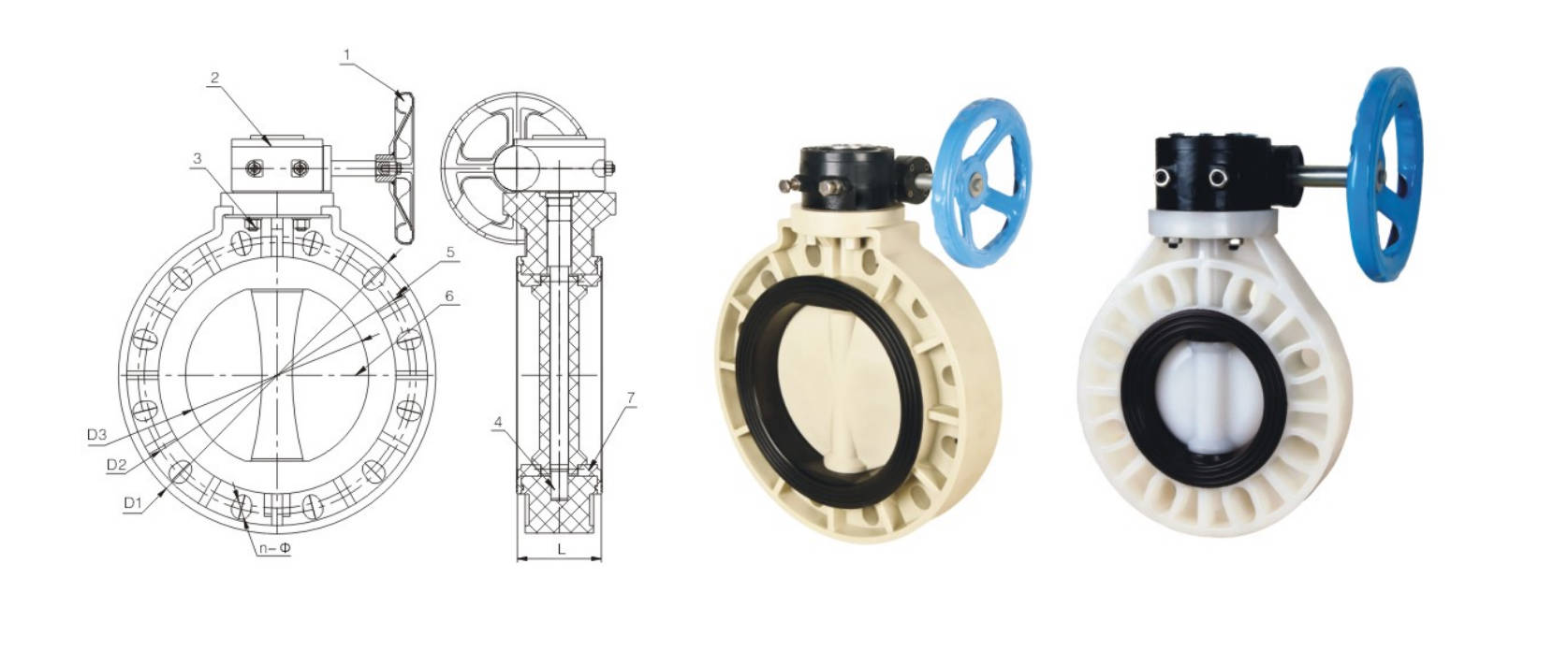
Dimensions Table
| DN (mm) | D1 | D2 (GB) | D2 (JIS) | D2 (ANSI) | D3 | L | n-Ø (GB) | n-Ø (JIS) | n-Ø (ANSI) |
|---|
| 40 (1 1/2") | 148 | 110 | 105 | 3.88 | 41.5 | 39 | 4-Ø19×25 | 4-Ø19×25 | 4-Ø19×25 |
| 50 (2") | 162 | 125 | 120 | 4.74 | 50 | 40 | 4-Ø19×26.5 | 4-Ø19×25.6 | 4-Ø19×25.6 |
| 65 (2 1/2") | 180 | 145 | 140 | 5.49 | 64 | 42 | 4-Ø19×26.5 | 4-Ø19×25.6 | 4-Ø19×25.6 |
| 80 (3") | 198 | 160 | 150 | 6.00 | 77 | 42 | 8-Ø19×25 | 8-Ø19×24 | 8-Ø19×25 |
| 100 (4") | 225 | 180 | 175 | 7.50 | 96 | 52 | 8-Ø19×32 | 8-Ø19×32 | 8-Ø19×32 |
| 125 (5") | 255 | 210 | 210 | 8.50 | 120 | 61 | 8-Ø23×33 | 8-Ø23×33 | 8-Ø23×33 |
| 150 (6") | 285 | 240 | 240 | 9.51 | 145 | 71 | 8-Ø23×34 | 8-Ø23×34 | 8-Ø22×34 |
| 200 (8") | 340 | 295 | 290 | 11.75 | 196.5 | 81 | 8-Ø23×33.5 | 12-Ø23×27 | 8-Ø22×33.5 |
| 250 (10") | 406 | 350 | 355 | 14.25 | 245.5 | 110 | 12-Ø23×23.5 | 12-Ø25×32.5 | 12-Ø25×32.5 |
| 300 (12") | 483 | 400 | 400 | 17.00 | 291.5 | 115 | 12-Ø23×42.5 | 16-Ø25 | 12-Ø26×42.5 |
| 350 (14") | 533 | 460 | 445 | 18.78 | 340 | 127 | 16-Ø23×25 | 16-Ø25 | 16-Ø30×32 |
| 400 (16") | 597 | 515 | 510 | 21.26 | 399 | 140 | 16-Ø23×43 | 16-Ø27 | 16-Ø30×43 |
| 450 (18") | 635 | 565 | 565 | 22.76 | 446 | 150 | 20-Ø26×28.5 | 20-Ø26×28.5 | 16-Ø32×34.5 |
| 500 (20") | 700 | 620 | 620 | 25.00 | 494 | 150 | 20-Ø26×44 | 20-Ø26×44 | 20-Ø32×44 |
| 600 (24") | 815 | 725 | 730 | 29.53 | 570 | 170 | 20-Ø35×47.5 | 24-Ø33 | 20-Ø35×47.5 |
| 700 (28") | 928 | 840 | 840 | 34.02 | 670 | 185 | 24-Ø31×44 | 24-Ø33 | 24-Ø35 |
| 800 (32") | 1060 | 950 | 950 | 38.50 | 755 | 220 | 24-Ø41×60 | 28-Ø33×39 | 24-Ø41×60 |
| 1000 (40") | 1230 | 1160 | 1160 | 46.26 | 935 | 236 | 28-Ø36×52 | 28-Ø39 | 32-Ø41 |
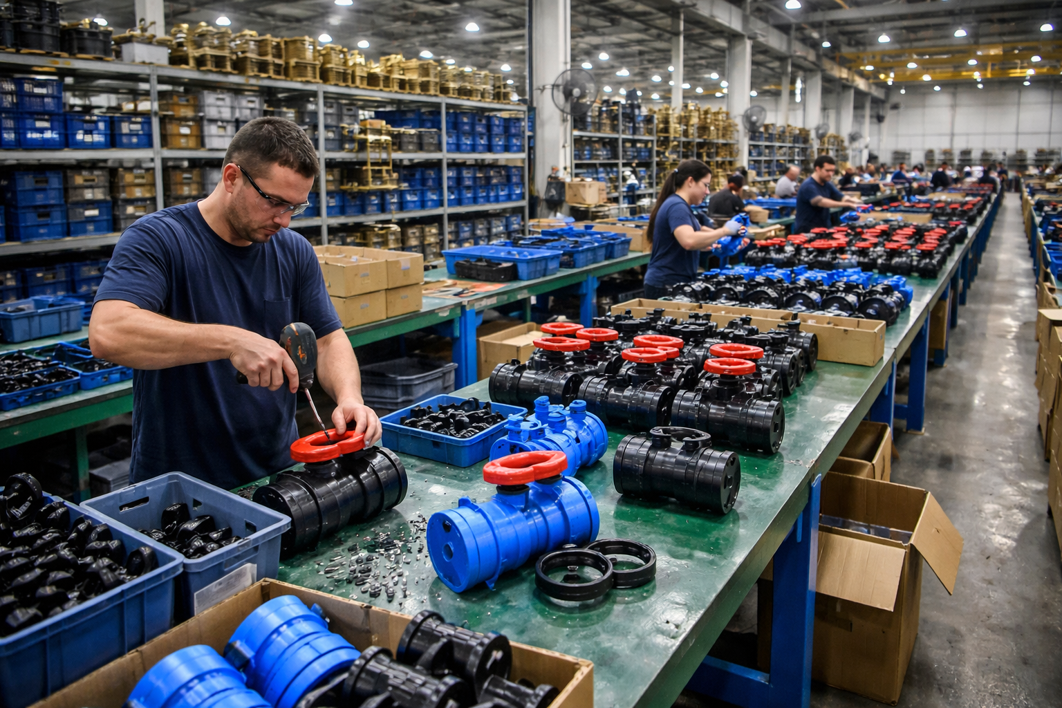
Manufacturing Process
Step 1: Order and Design
Based on customer requirements, determine the dimensions, pressure rating, connection standards (e.g., DIN/ANSI), and materials (e.g., PVC/CPVC/PP) for the turbo butterfly valve. Complete the structural design and confirm the drawings, including the design of the valve body, disc, and turbo actuator.
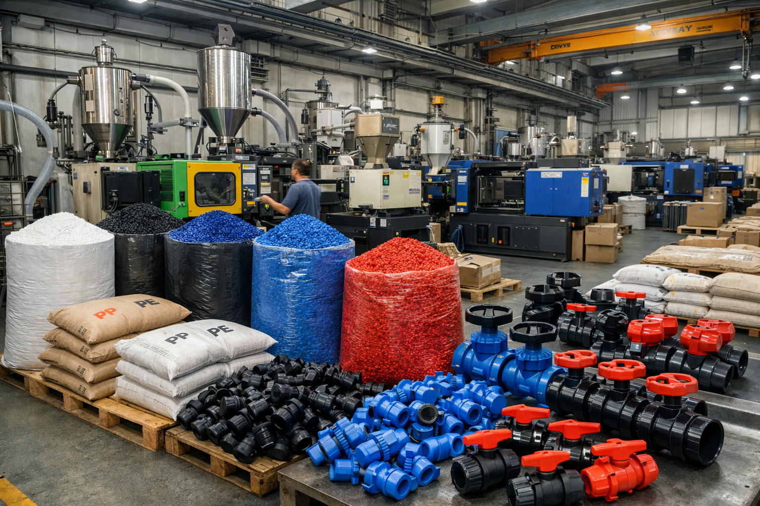
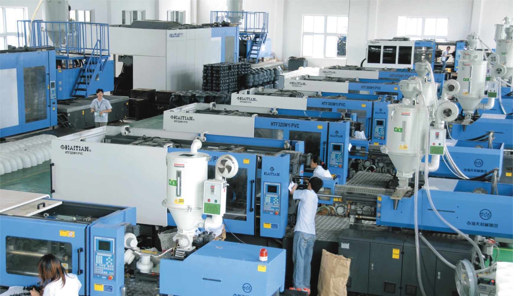
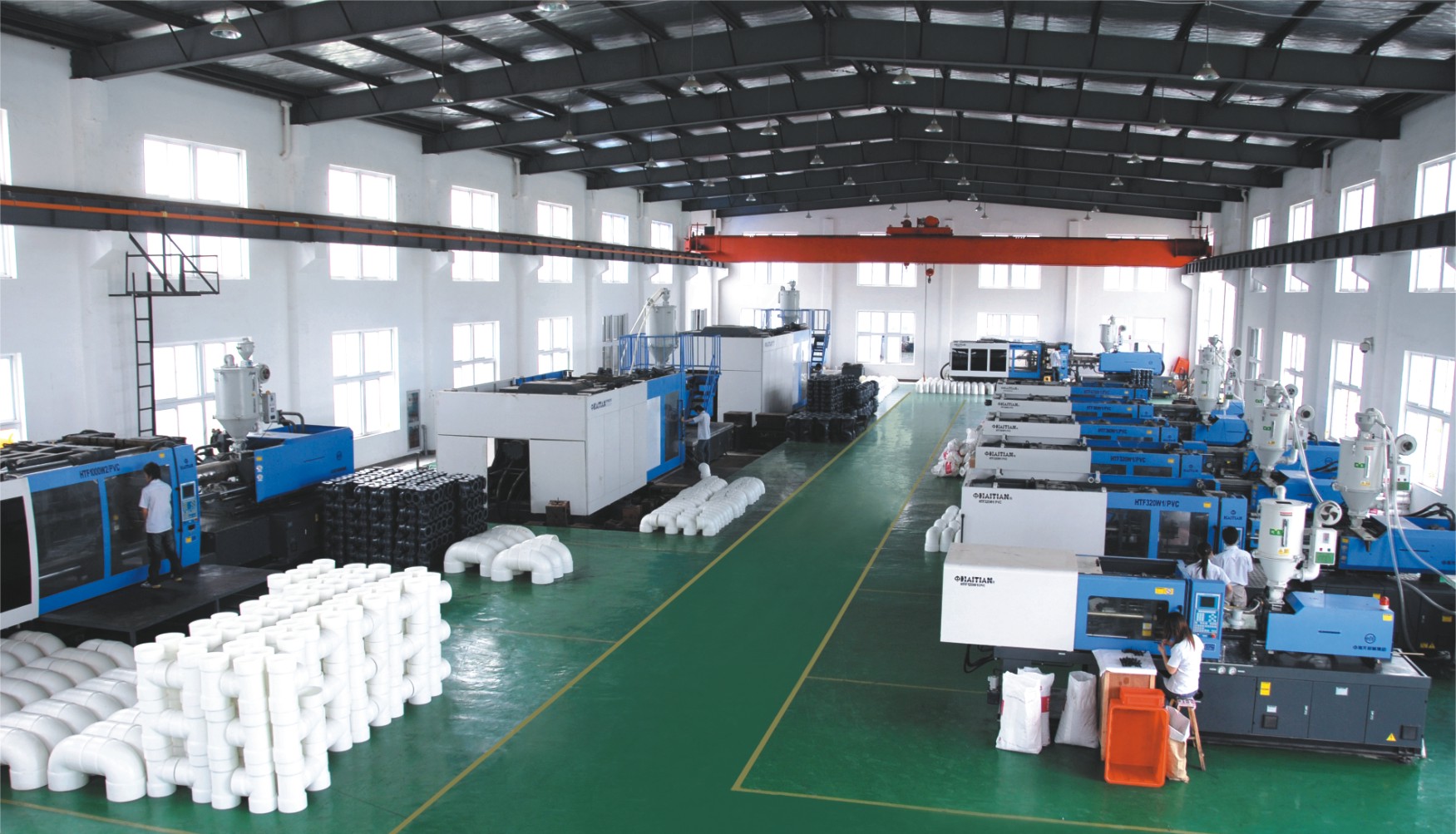
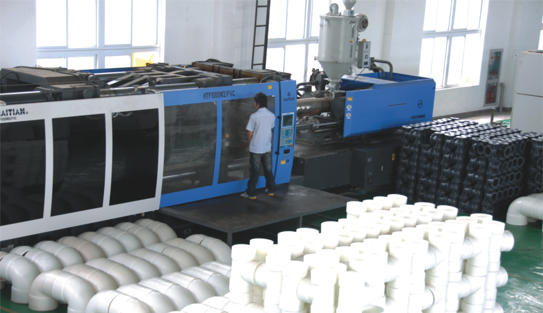
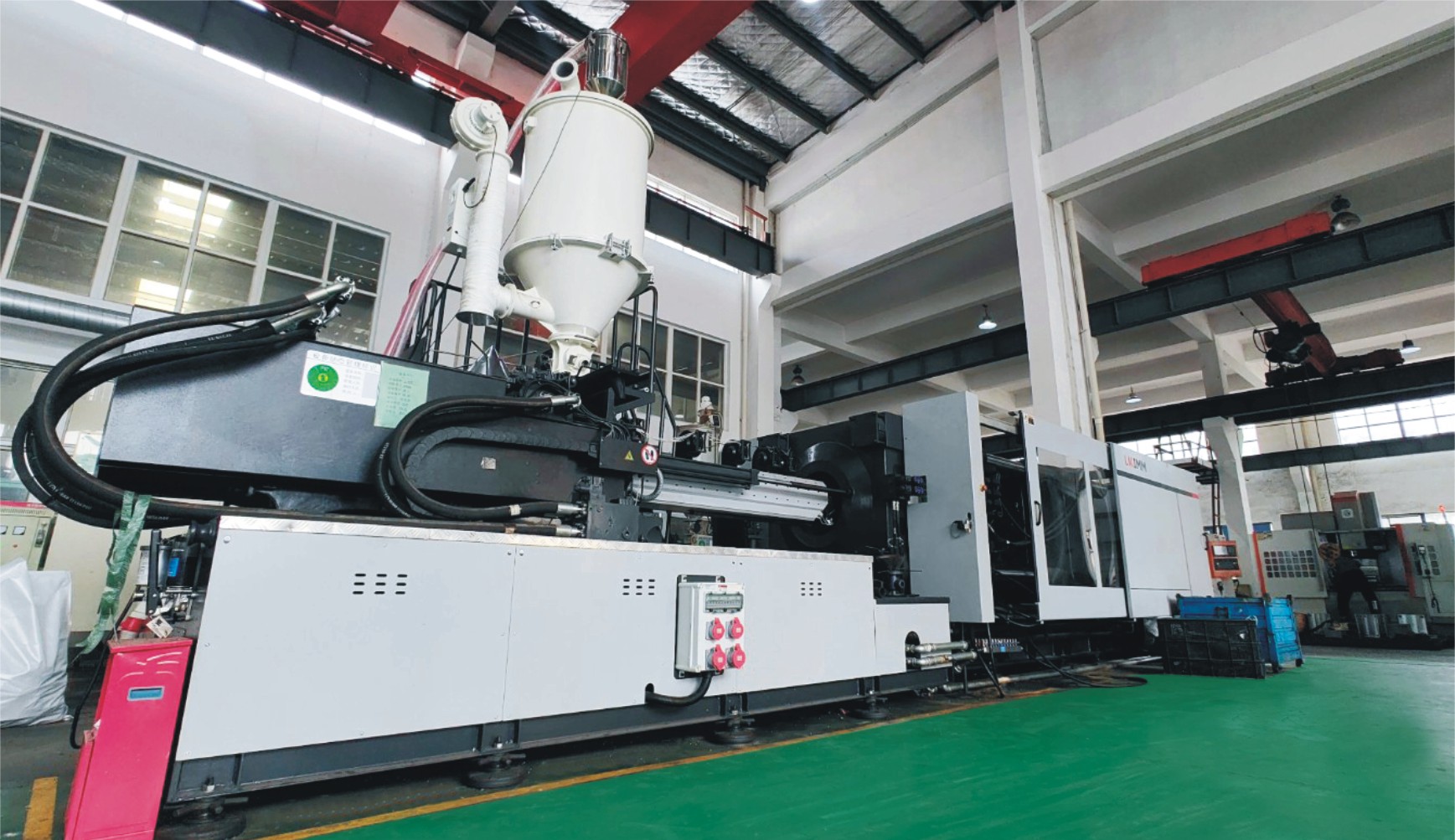
Step 2: Raw Material Preparation & Molding
Select high-quality plastic raw materials, dry them, and then process the valve body, disc, and certain structural components of the turbo butterfly valve via injection molding or compression molding to ensure material uniformity and dimensional stability.
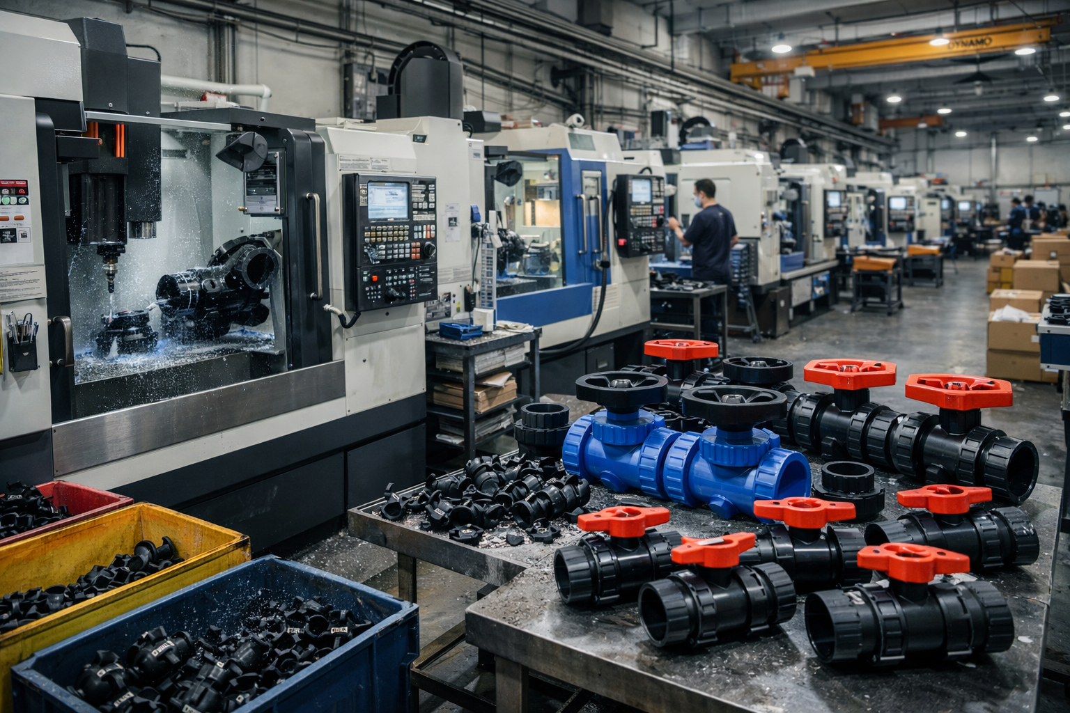
Step 3: Machining
Machine the molded turbo butterfly valve components to precision, including turning of sealing surfaces, drilling of holes, and flange surface finishing, to ensure fitting accuracy and sealing performance.
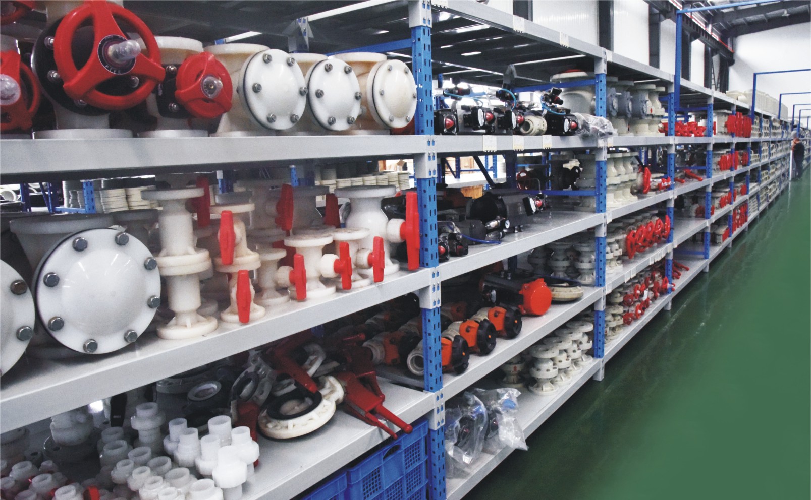
Step 4: Assembly
Assemble the valve body, disc, seal rings, and gear operator to complete the turbo butterfly valve assembly, while adjusting the transmission mechanism to ensure smooth opening and closing without sticking.
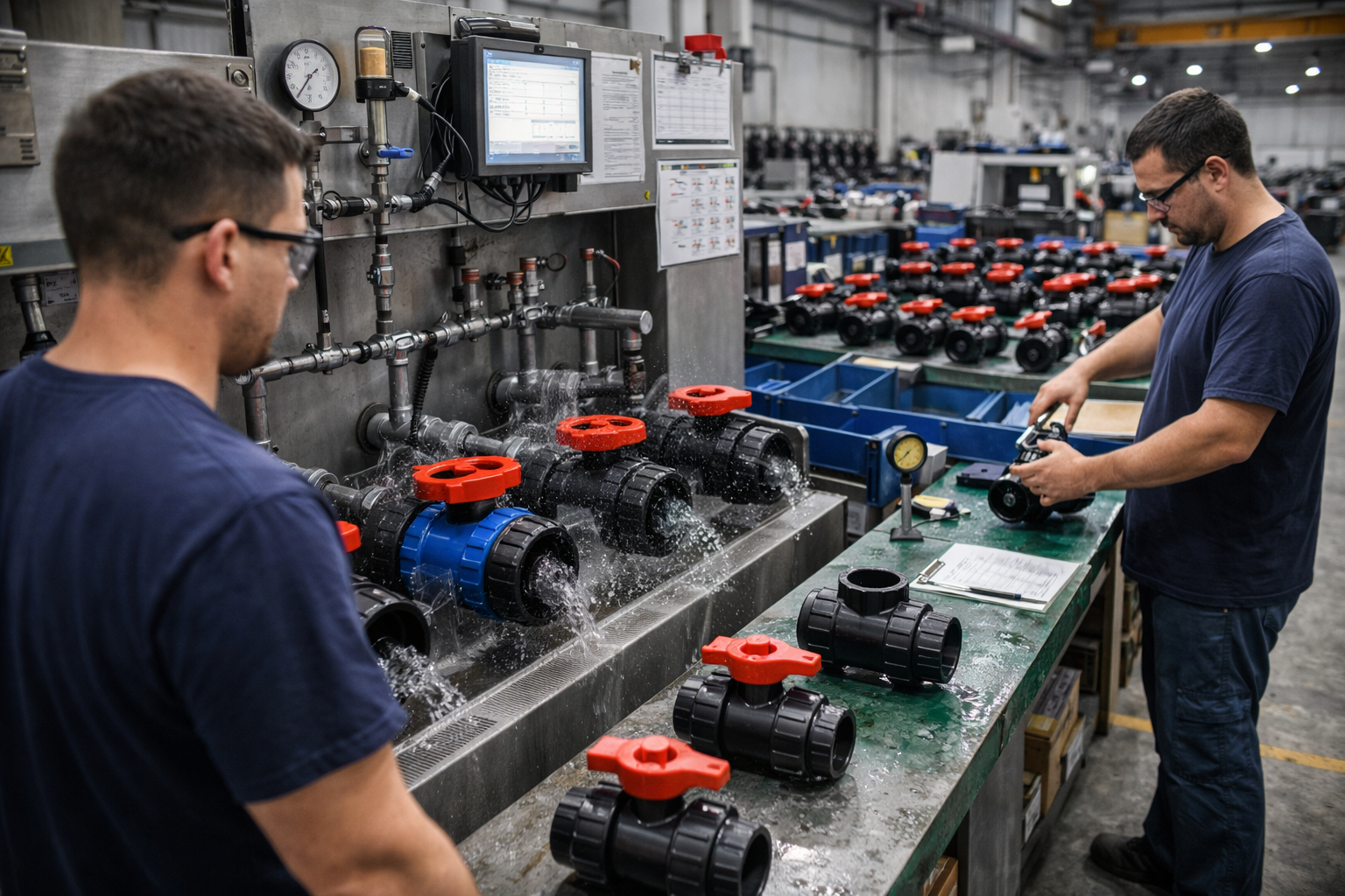
Step 5: Testing & Quality Assurance
The assembled turbo butterfly valve undergoes seal testing, pressure testing, and operating torque testing to ensure compliance with relevant standards (such as ISO/API) and customer requirements.
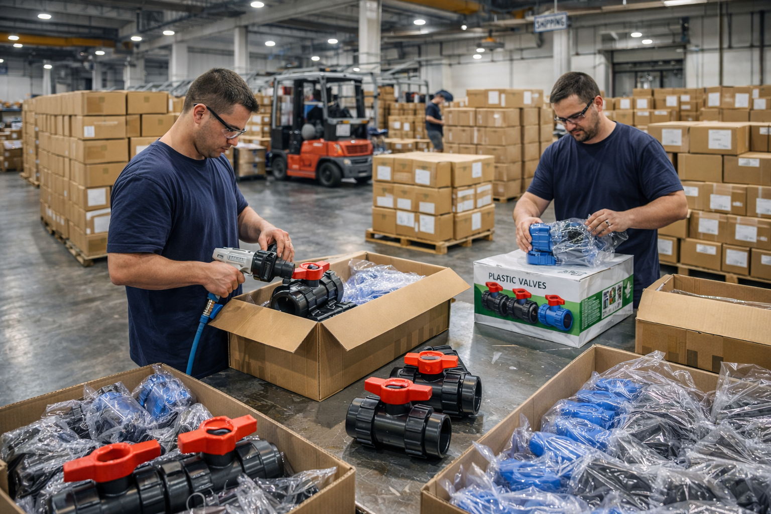
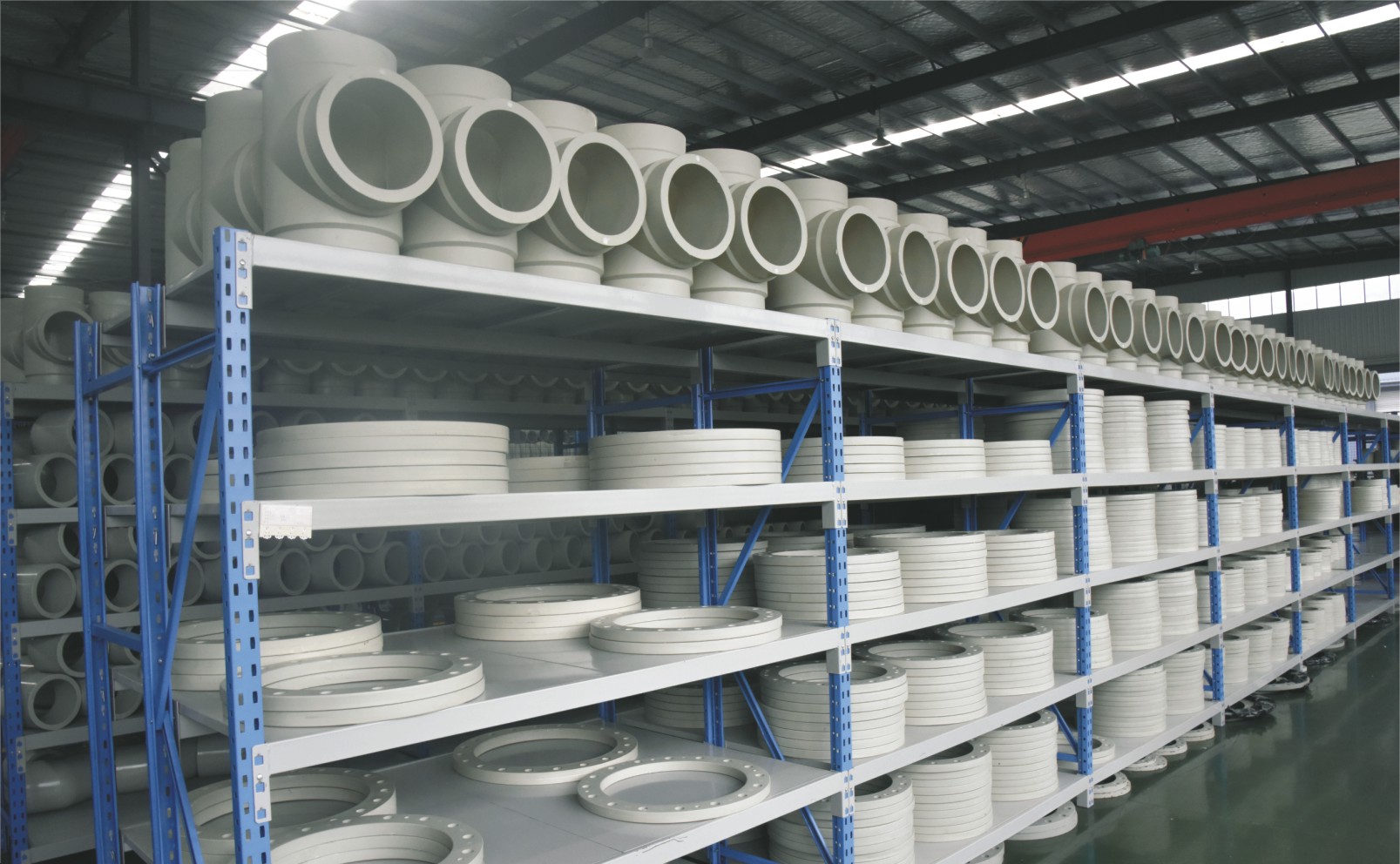
Step 6: Finishing, Packaging and Shipment
The product is cleaned and protected, clearly labeled, and packaged (in cardboard or wooden crates). Shipment is arranged to ensure the turbo butterfly valve remains undamaged during transit.
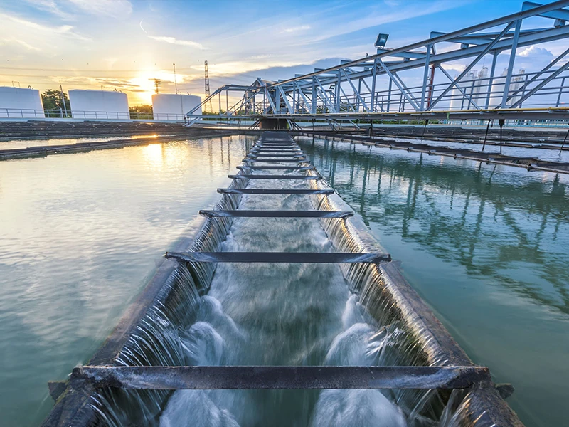
Applications
Turbo butterfly valve is an industrial valve controlled by a worm gear drive mechanism. It is widely used in industrial piping systems—such as those in the metallurgy, power generation, petrochemical, water supply and drainage, and fire protection industries—where the medium temperature is high, serving to shut off, connect, and regulate flow.
These valves are widely used in:
Agriculture and Irrigation
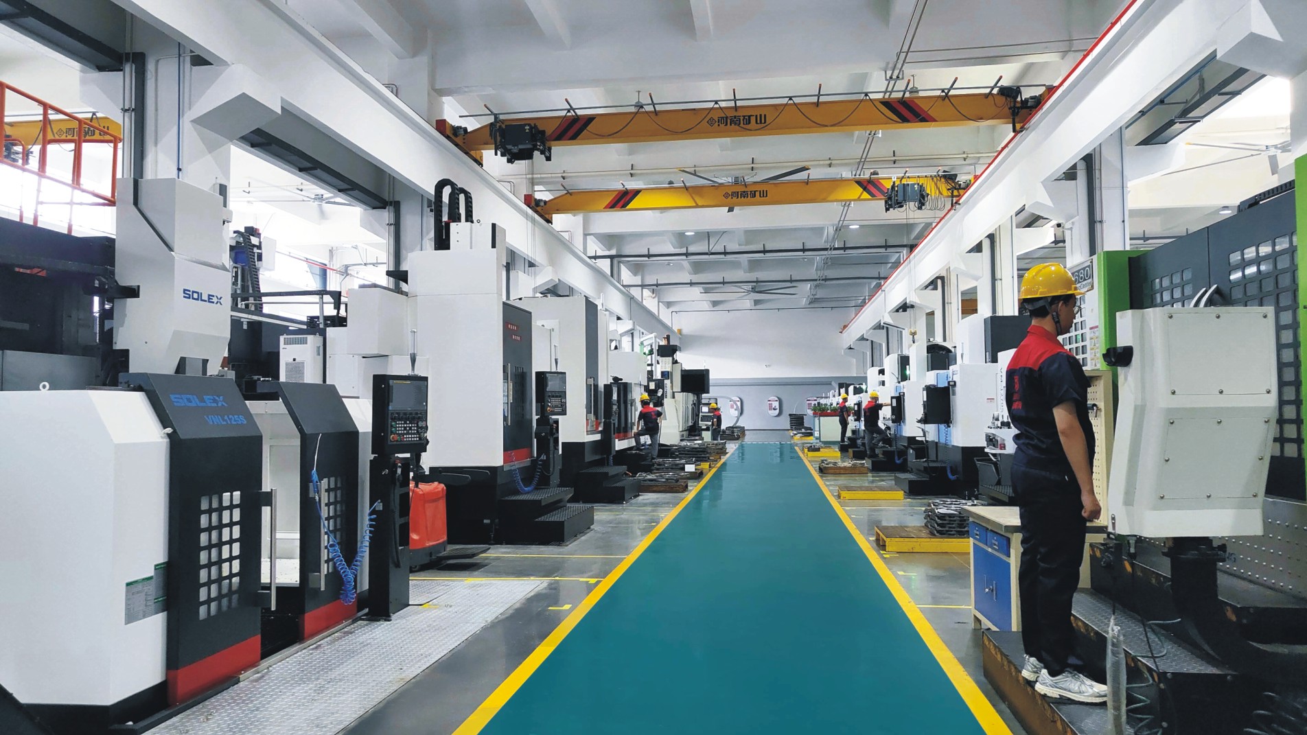
Factory Environment
Why Choose Us
Superior Quality
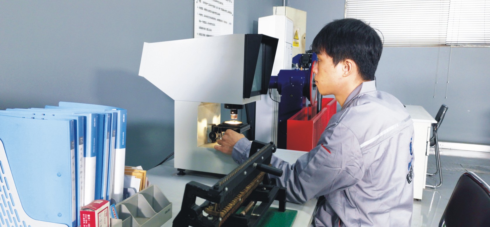
Our valves are produced from high-grade materials and subjected to strict quality inspections to guarantee dependable performance in challenging industrial environments.
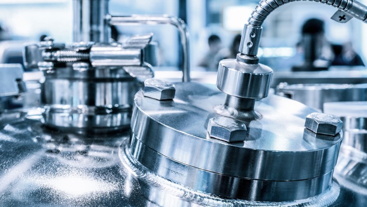
Advanced Technology
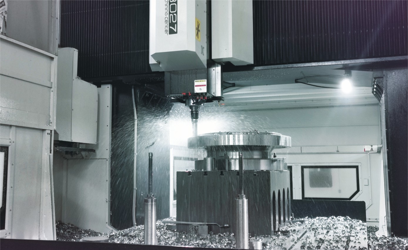
With cutting-edge CNC machining systems and high-precision manufacturing equipment, we ensure valves are made with outstanding accuracy and uniformity.
Competitive Pricing
By streamlining production processes and sourcing materials in bulk, we provide premium-quality valves at competitive prices while maintaining excellent standards.
Expert Support
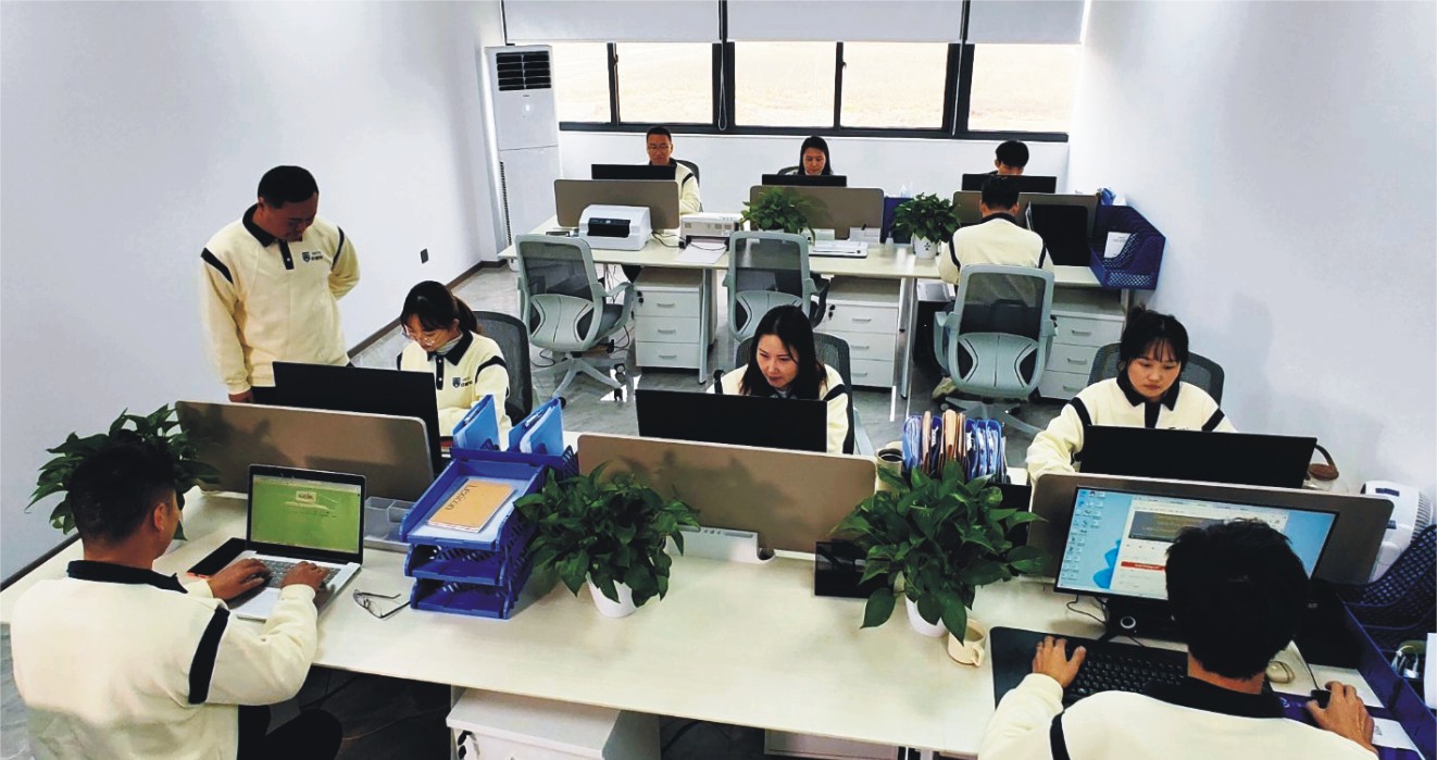
Our skilled technical team offers full support from product selection through after-sales service, helping ensure the best valve performance for your application.